
Apparatus and method for compressing a gas, and cryosurgery system and method utilizing same

a gas compression and apparatus technology, applied in the field of apparatus and apparatus for compressing and/or recompressing gas, can solve the problems of compromising the purity of compressed gas, limiting and disadvantages of these prior art methods, and affecting the operation of surgical instruments for cooling,

Inactive Publication Date: 2008-08-05
GALIL MEDICAL
View PDF60 Cites 59 Cited by
  • Summary
  • Abstract
  • Description
  • Claims
  • Application Information

AI Technical Summary

Benefits of technology

This approach eliminates the need for lubrication, allows for efficient use of gas at constant pressure, reduces waste, and enables the practical and economical use of rare and expensive gases by re-pressurizing and reusing them, thereby overcoming the limitations of prior art in gas compression and utilization.

Problems solved by technology

With respect to some applications, however, limitations and disadvantages of these prior art methods are apparent.
Reciprocating piston compression systems typically require lubrication, and volatilization of the lubricants can compromise the purity of the compressed gas.
The prior art methods of supplying high pressure gas to high pressure gas applications are problematic in several respects.
One practical problem encountered in using high pressure gas in applications is that some high pressure gasses are simply not commercially available in many regions of the world.
This problem exists even in some highly industrialized regions.
In Japan, for example, argon gas, which is used in welding and other industrial processes, is available in popular industrial medium-pressure concentrations, yet high pressure argon gas is not commercially available in Japan.
A second practical problem in the use of prior art methods for supplying high pressure gas to a high pressure gas application is that transporting high pressurize gas can be inconvenient and / or dangerous.
Transportation is more problematic as well.
It may be considered more dangerous to transport high pressurize gas by air transportation, for example.
A third problem in the use of prior art methods for supplying gas to high pressure gas applications is that a significant portion of gas so supplied cannot be used for its intended purpose.
At this point, considerable gas still remains in the container.
This situation has the practical disadvantage that the container must then be returned to the gas supplier for refilling while still containing a significant quantity of unused gas, which is inconvenient.
It also has the commercial disadvantage that in many cases suppliers do not credit their customers for the returned gas, so that the customer often pays for gas which was supplied to him but which he could not use.
There are, of course, some compressed gas utilizing applications in which re-pressurization and re-use of gasses is impractical.
In some uses of compressed gas the cost of pressurizing and transporting the gas is relatively greater than the cost of manufacturing or isolating the gas.
Here too, recycling the gas is not generally practical.
This is the case, for example, in compressed gas utilizing applications utilizing a gas which is rare, or is expensive to produce or to isolate, and in which the gas is not chemically transformed when utilized.
Yet krypton is considerably more expensive than argon, on the order of one hundred times more expensive in today's market.
In a prior art system, where the compressed gas used in cryosurgery is, after decompression through use, simply vented to the atmosphere, use of the otherwise desirable krypton gas would be wasteful and expensive.
The limitations and disadvantages of the prior art in the field of gas compression and the use of compressed gasses are particularly clear in the context of cryosurgery.
However all such methods have the common disadvantage that while they raise the temperature of the tissues whose destruction is intended, they transfer heat to healthy tissues as well, causing their destruction, partial destruction, or functional impairment.
Moreover, in some cases tissues exposed to thermal energy or other forms of energy that raise their temperatures secrete substances toxic to adjacent healthy tissues.
Expansion of the gas causes it to cool and may cause it to liquefy, or further liquefy.
The need for high pressure gasses for efficient operation of cryosurgical equipment raises the several practical problems discussed hereinabove.
High pressure argon is more expensive than argon at standard industrial pressures, and in some locations, such as Japan, high pressure argon is not available at all.
An additional problem connected with the high-pressure requirements of cryosurgery is that even in regions of the world where high-pressure cooling and heating gasses are commercially available, their utilization is awkward and expensive.
According to the methods of prior art, once pressure in a gas supply container falls below the minimum pressure required for cryosurgery, the gas supply container can no longer be utilized as a cryosurgery gas source, despite the fact that a considerable amount of cooling (or heating) gas may yet remain in the tank.
In either case, the expense and bother occasioned by the necessity of switching containers, and the necessity of returning containers to a supplier for refilling while they yet contain substantial amounts of useful gas, are significant disadvantages of cryosurgical equipment and procedures, according to the known methods of prior art.
Prior art cryosurgery systems also suffer from the disadvantage that they do not re-use pressurized gas.
Yet, it is largely impractical to use Krypton gas in prior art cryogenic systems, wherein the cooling gas is used for cryogenic cooling only once, and then is allowed to escape to the atmosphere.

Method used


Image

  • Apparatus and method for compressing a gas, and cryosurgery system and method utilizing same
  • Apparatus and method for compressing a gas, and cryosurgery system and method utilizing same
  • Apparatus and method for compressing a gas, and cryosurgery system and method utilizing same

Examples


Embodiment Construction

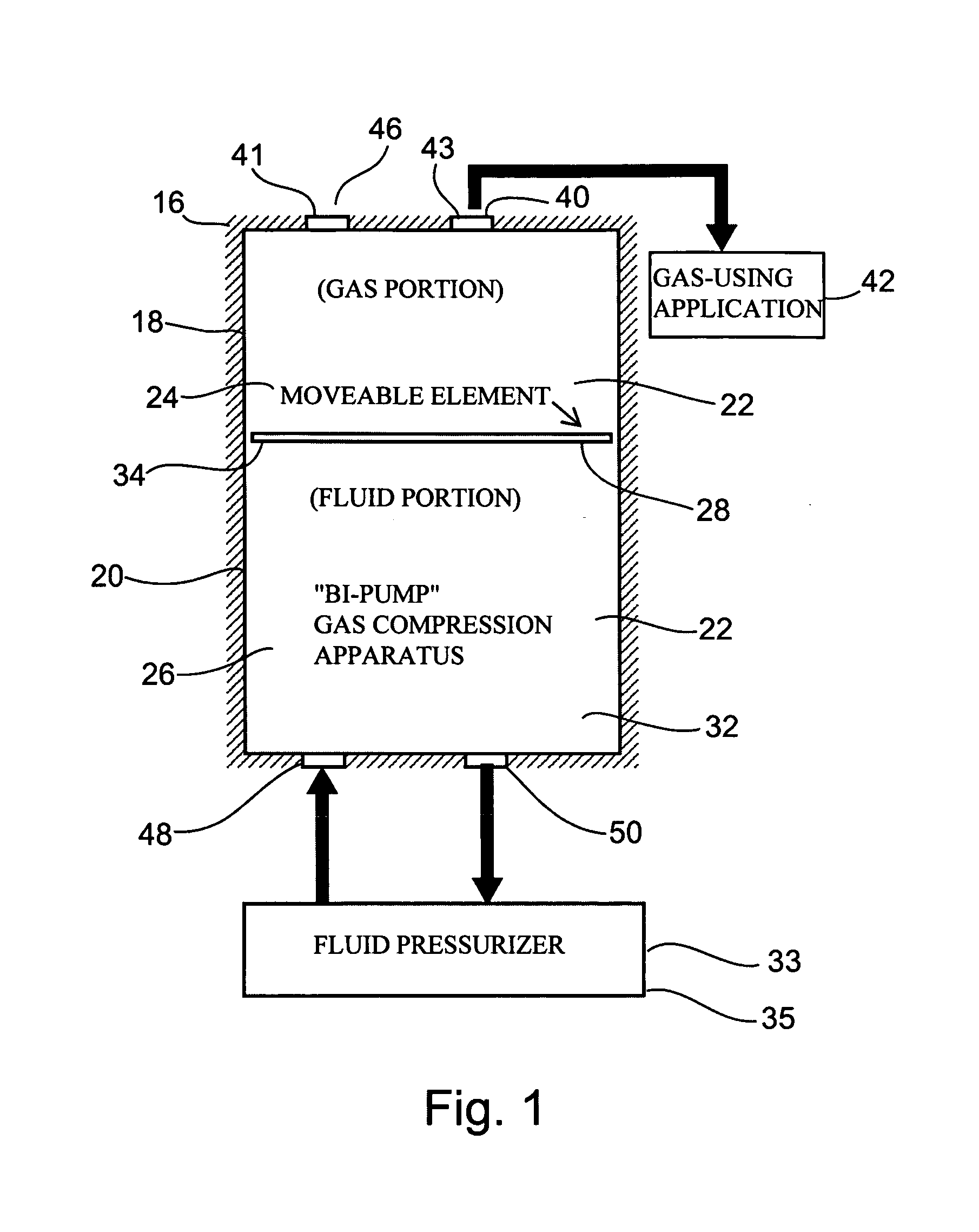
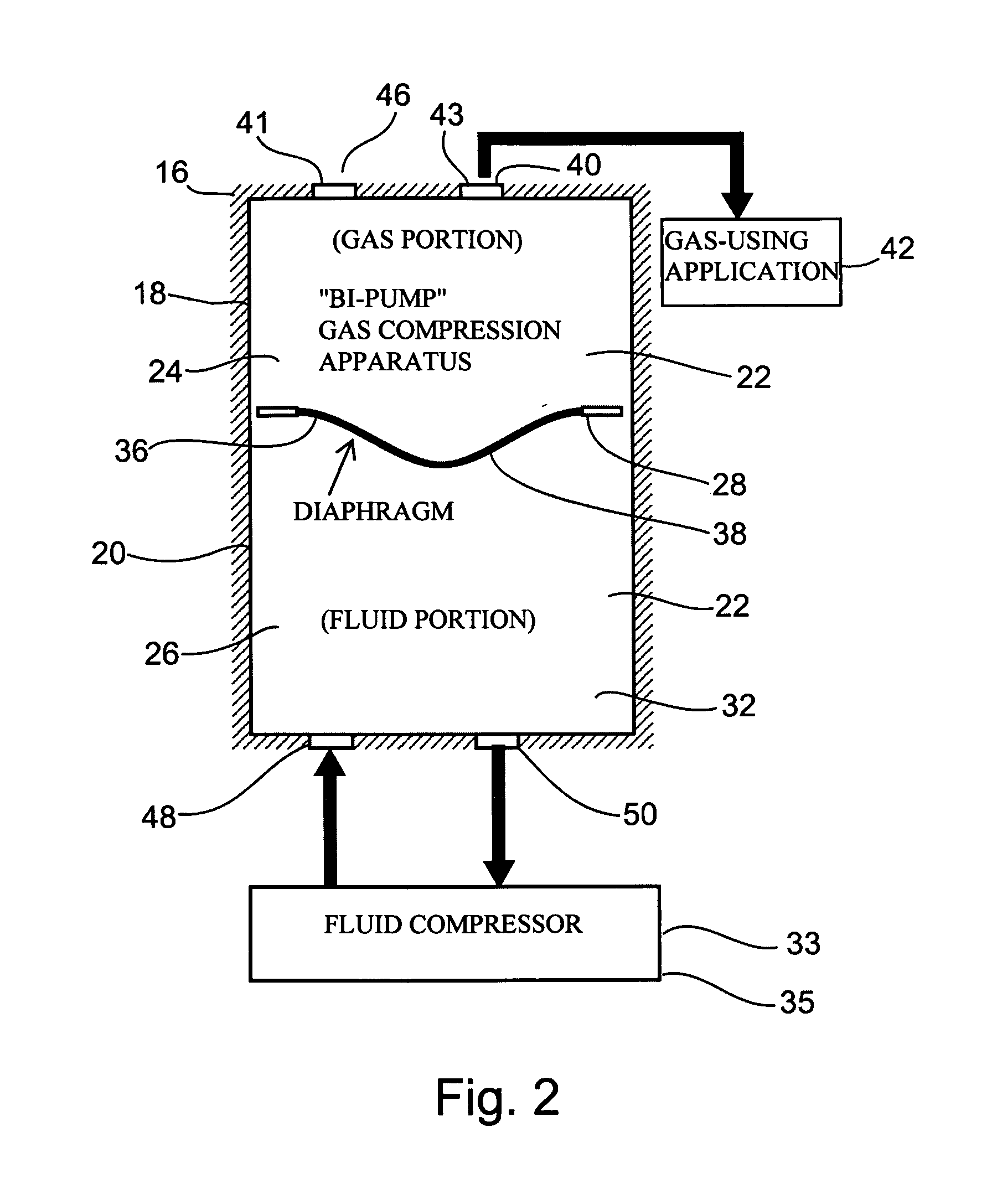
[0076]The present invention is of apparatus and method for compressing and / or re-compressing gas which can be used for in situ gas compression as a method of supplying compressed gas to a compressed gas utilizing application, such as a cryoablation apparatus. More specifically, the present invention can be used to compress a gas for use in a compressed gas utilizing application. The present invention can further be used to raise the pressure of a compressed gas, to thereby supply high pressure gas to a compressed gas utilizing application using medium pressure gas sources. It can further be used to supply compressed gas at a constant selected pressure to a compressed gas utilizing application. It can further be used to supply compressed gas to a compressed gas utilizing application, while utilizing all or substantially most of the gas supplied in conventional gas cylinders or similar containers.

[0077]In one particular and presently preferred embodiment, the present invention is used...


PUM


Abstract

An apparatus for compressing a gas and its uses are disclosed. The apparatus comprises a fixed-volume container having a hollow and a moveable element subdividing said hollow into a first variable-volume portion and a second variable-volume portion, the second variable-volume portion having an opening for introducing therein a hydraulic and / or pneumatic fluid under pressure, for causing an increase in the volume of said second variable-portion by moving said moveable element, thereby, consequently, decreasing the volume of the first variable-volume portion and compressing a gas contained therein.

Description

[0001]This is a continuation of U.S. patent application Ser. No. 09 / 987,689, filed Nov. 15, 2001 which is abandoned, which is a continuation-in-part of U.S. patent application Ser. No. 09 / 860,486, filed May 21, 2001, now U.S. Pat. No. 6,706,037, which claims the benefit of priority from U.S. Provisional Patent Application No. 60 / 242,455, filed Oct. 24, 2000, now expired.FIELD AND BACKGROUND OF THE INVENTION[0002]The present invention relates to apparatus and method for compressing and / or re-compressing gas and further to the use of in situ gas compression as a source of compressed gas to a compressed gas utilizing application, such as a cryoablation apparatus.[0003]Many methods are known in the art for mechanically compressing (pressurizing) gas, for storing compressed (pressurized) gas in containers, for transporting compressed gas to sites where the compressed gas is to be used, and for utilizing compressed gasses for a variety of purposes in a variety of utility applications.[000...

Claims


Application Information

Patent Timeline
Patent Type & Authority Patents(United States)
IPC IPC(8): A61B18/02A61B5/055G01R33/28A61B5/06A61B6/00A61B6/03A61B6/12A61B8/00A61B17/00A61B17/34A61B18/00A61B19/00
CPCA61B18/02A61B19/52A61B2017/00092A61B2017/00867A61B2018/00041F17C2201/019A61B2018/0268A61B2018/0287F17C2201/018F17C2201/0185A61B2018/0262A61B90/36
Inventor ZVULONI, RONI
Owner GALIL MEDICAL
Learn More