
Method for the synthesis of VLSI systems based on data-driven decomposition

a data-driven decomposition and synthesis technology, applied in the field of vlsi (very large scale integration) circuit design, can solve the problems of abandoning syntax-directed approach, many chip designers are deterred from taking advantage of these qualities, and many transistors are complex and highly concurrent, so as to reduce forward latency, improve energy and performance, and reduce energy consumption

Inactive Publication Date: 2008-07-22
CALIFORNIA INST OF TECH
View PDF4 Cites 6 Cited by
  • Summary
  • Abstract
  • Description
  • Claims
  • Application Information

AI Technical Summary

Benefits of technology

[0016]Instead of being dictacted by the syntax of the input program, the decomposition method of the present invention examines data dependencies in the process' computation, and then attempts to eliminate unnecessary synchronization in the system. Depending on the flow of data in the original process, concurrency may be added into the system through decomposition. To avoid dealing with mutual exclusion problems, no shared variables or communication channels are permitted. The decomposed processes transfer data by explicitly communicating with each other.Data Driven Decomposition (DDD) Process
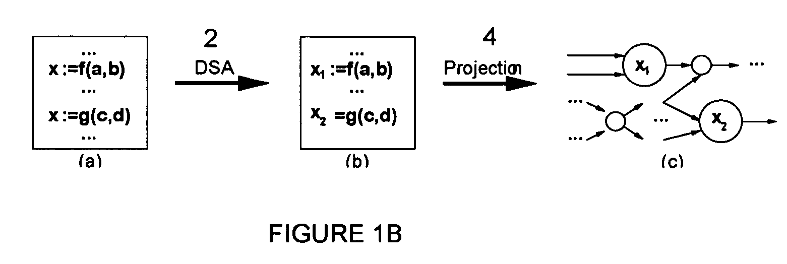
[0019]The overall decomposition approach specifies that each target process consist of all of the assignments that occur in the source process to a particular variable. Converting the source process into DSA form can reduce the number of assignments to a variable and hence simplify the target processes of a decomposition. Since simple target processes make the post-decomposition steps of synthesis easier, one thing that the DSA conversion does is to take variables with multiple assignments in the source process and split them to create new DSA variables.
[0028]The processes in a decomposed system produced by the process of DSA conversion and projection are slated for clustering. Recomposing DDD modules into larger modules further improves energy and performance. DDD modules can be clustered together with different goals in mind: reducing energy consumption, reducing forward latency, or reducing the time and energy-efficiency metric Et2. An example of clustering optimization is illustrated in FIG. 5, where graph 60 shows a system before clustering and graph 62 shows the equivalent system after clustering.
[0029]Clustering is implemented in two stages. In the first stage, DDD modules along the critical path of a system are repeatedly clustered in series until they are too large to be implemented as single PCHB stages. The second stage requires a global optimization algorithm (e.g. quadratic programming, simulated annealing, and genetic algorithms) to both cluster DDD modules in parallel and add slack-matching buffers to improve performance.

Problems solved by technology

Many chip designers, however, are deterred from taking advantage of these qualities by the lack of a straightforward design approach.
In designing asynchronous VLSI systems, the formal synthesis of asynchronous VLSI systems begins with a sequential description of the circuit specification and results in a complex and highly concurrent network of transistors.
For example, the designers of the asynchronous MIPS R3000 saw that very fine-grained pipeline stages were required to achieve high throughput, and abandoned the syntax-directed approach because it could not generate modules that were small enough.

Method used


Image

  • Method for the synthesis of VLSI systems based on data-driven decomposition
  • Method for the synthesis of VLSI systems based on data-driven decomposition
  • Method for the synthesis of VLSI systems based on data-driven decomposition

Examples


Embodiment Construction

[0044]The present invention relates to the field of VLSI circuit design, and in particular to a method for VLSI synthesis based on data-driven decomposition (DDD). Embodiments of the present invention comprise of methods that aid the design of VLSI circuit by formalizing and automating decomposition based on data dependencies.

[0045]In the present invention, the basic units of decomposition are assignments to a variable (whether through a communication with another process or an actual assignment statement). The goal is to give every variable in the source process its own target process that implements all assignments to that variable. These target processes mostly conform to a basic template. To keep the target processes simple enough for future synthesis, the decomposition method must control the number of assignments to each variable in the source process.

[0046]One decomposition method embodiment is comprised of three stages. First, the source process is converted into Dynamic Sin...


PUM


Abstract

The present invention is a systematic and data-driven-decomposition (DDD) method and apparatus for use in VLSI synthesis. The invention decomposes a high level program circuit description into a collection of small and highly concurrent modules that can be implemented directly into transistor networks. This enables an automatic implementation of a decomposition process currently done by hand. Unlike prior art syntax-based decompositions, the method of the present invention examines data dependencies in the process' computation, and then attempts to eliminate unnecessary synchronization in the system. In one embodiment, the method comprises: a conversion to convert the input program into an intermediate Dynamic Single Assignment (DSA) form, a projection process to decompose the intermediate DSA into smaller concurrent processes, and a clustering process that optimally groups small concurrent processes to make up the final decomposition. Another embodiment is a decomposition, projection, and clustering tool implemented in computer program codes.

Description

[0001]This application claims the benefit of U.S. Provisional Patent Application No. 60 / 435,502, filed on Dec. 19, 2002, the disclosure of which is hereby incorporated by reference.[0002]The invention was made by an agency of the United States Government or under a contract with an agency of the United States Government. The name of the U.S. Government agency is DARPA and the Government contract number F29601-00K-0184.[0003]Portions of the disclosure of this patent document contain material that is subject to copyright protection. The copyright owner has no objection to the facsimile reproduction by anyone of the patent document or the patent disclosure as it appears in the Patent and Trademark Office file or records, but otherwise reserves all copyright rights whatsoever.BACKGROUND OF THE INVENTION[0004]1. Field of the Invention[0005]The present invention relates to the field of VLSI (Very Large Scale Integration) circuit design, and in particular to a method for VLSI synthesis bas...

Claims


Application Information

Patent Timeline
IPC IPC(8): G06F17/50
CPCG06F17/5045G06F30/30
Inventor WONG, CATHERINE G.NYSTROEM, MIKAMARTIN, ALAIN J.
Owner CALIFORNIA INST OF TECH
Learn More