Eureka AIR delivers breakthrough ideas for toughest innovation challenges, trusted by R&D personnel around the world.

Uniform illumination system

a technology of uniform illumination and optical system, applied in lighting applications, instruments, applications, etc., can solve the problems of low angle conversion efficiency, difficult, if not impossible, to collect all the emitted optical power using most mirrors and lenses,

Inactive Publication Date: 2008-07-15
SNAPTRACK
View PDF7 Cites 285 Cited by
  • Summary
  • Abstract
  • Description
  • Claims
  • Application Information

AI Technical Summary

Benefits of technology

[0007]It is another object of the system to provide a novel light source panel system and method for providing efficient and homogeneous rear illumination for such images as those represented by LCD screens.
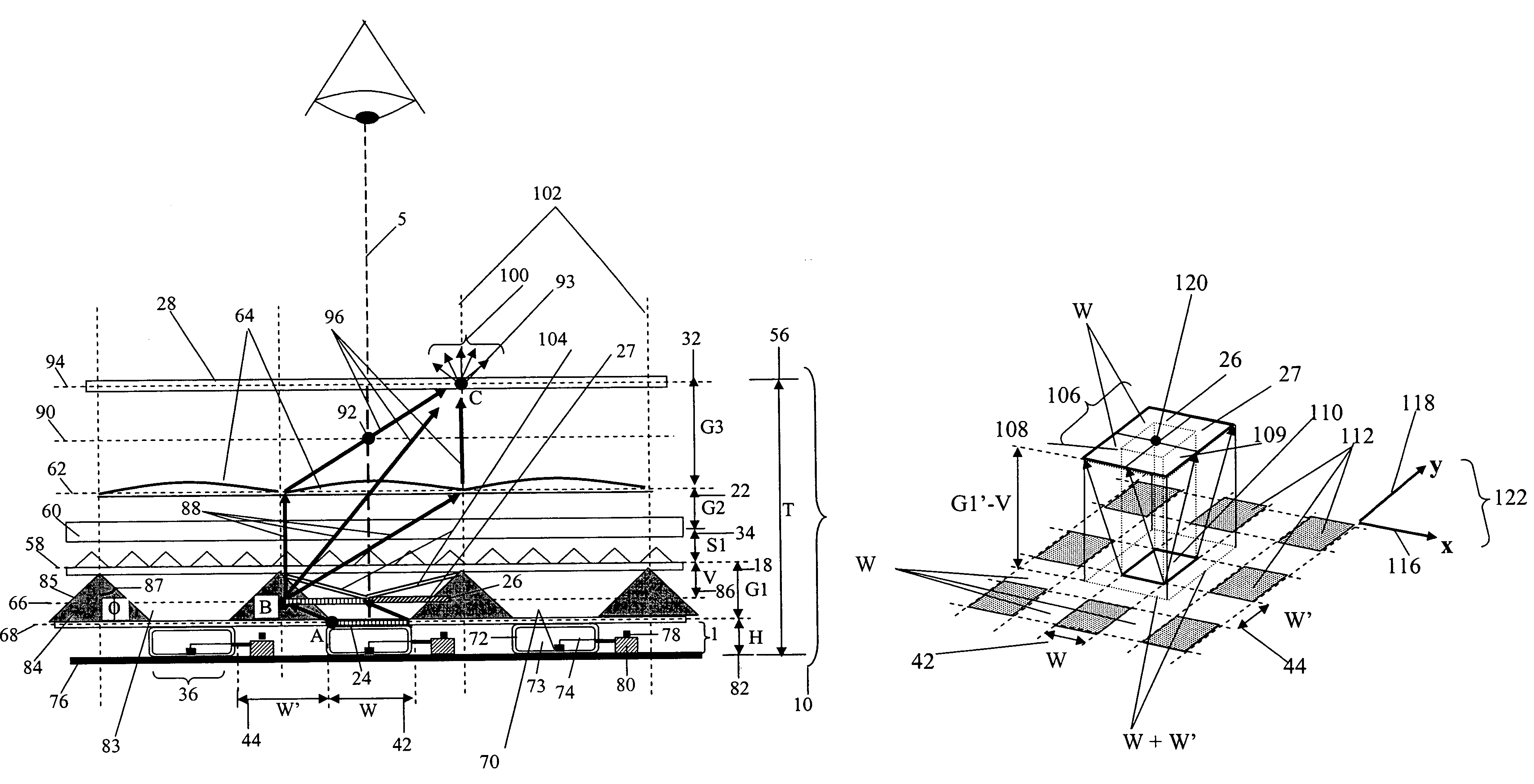
[0030]It is yet another object of the invention to provide an improved system and a method for homogenizing the uneven light distribution presented by a discontinuous two-dimensional array of light emitting diodes or regions containing light emitting diodes, each diode (or diode containing region) having length and width W, and equal separation from adjacent regions, W (or less than W), by using two parallel but orthogonal sheets of linear micro prisms, the exact elevation of these sheets from the emitting plane set approximately at height generally between W and 0.5W, so as to produce maximum evenness of output brightness within the output beam so created.

Problems solved by technology

The main problem with using such raw wide-angle LED output efficiently enough is that it is difficult, if not impossible, to collect all the emitted optical power using most mirror and lens based angle transforming optical systems such as those employed in FIGS.
Doing so definitely increases the amount of usable output light yielded from the device as compared with the amount of light yielded from a flat (no-lens) output surface, but the efficiency of angle conversion is low.
A simple one surface lens is not able to handle as wide an angular input range as the diode emits, and because of this, a large fraction of the emission is transmitted outside the angular range desired.
The further the device aperture to be illuminated is separated from transformer output aperture 702, the more that aperture will be inefficiently over-filled by a larger field of light.
The principal drawbacks of this approach, compared to those used in the present inventions, is a comparative lack of compactness and spatial uniformity.
The reason for the relative lack of compactness is the fact that efficient imaging systems require using several lenses with object and image separated from the lens's focal planes by finite distances.

Method used


Image

  • Uniform illumination system
  • Uniform illumination system
  • Uniform illumination system

Examples


Embodiment Construction

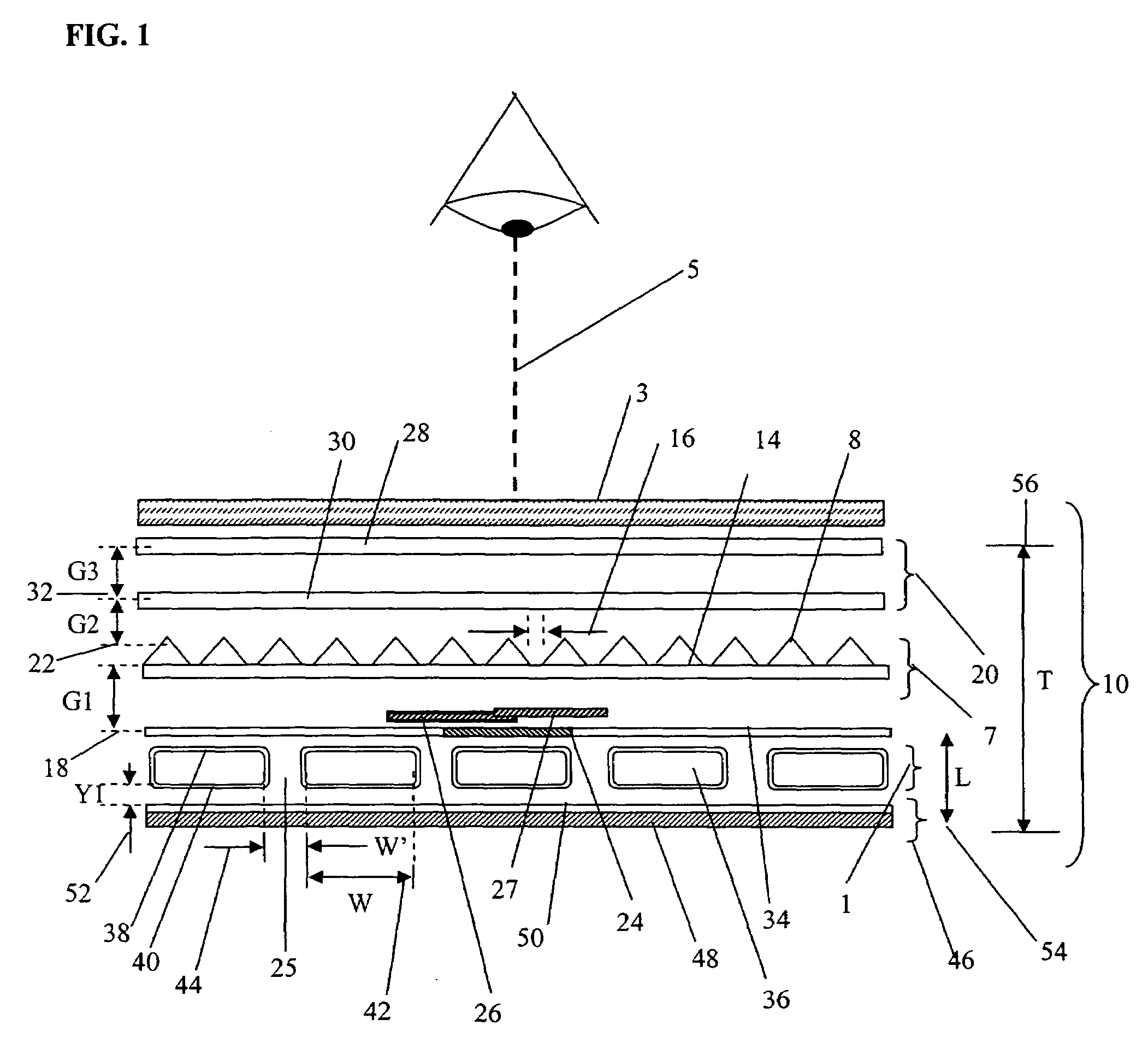
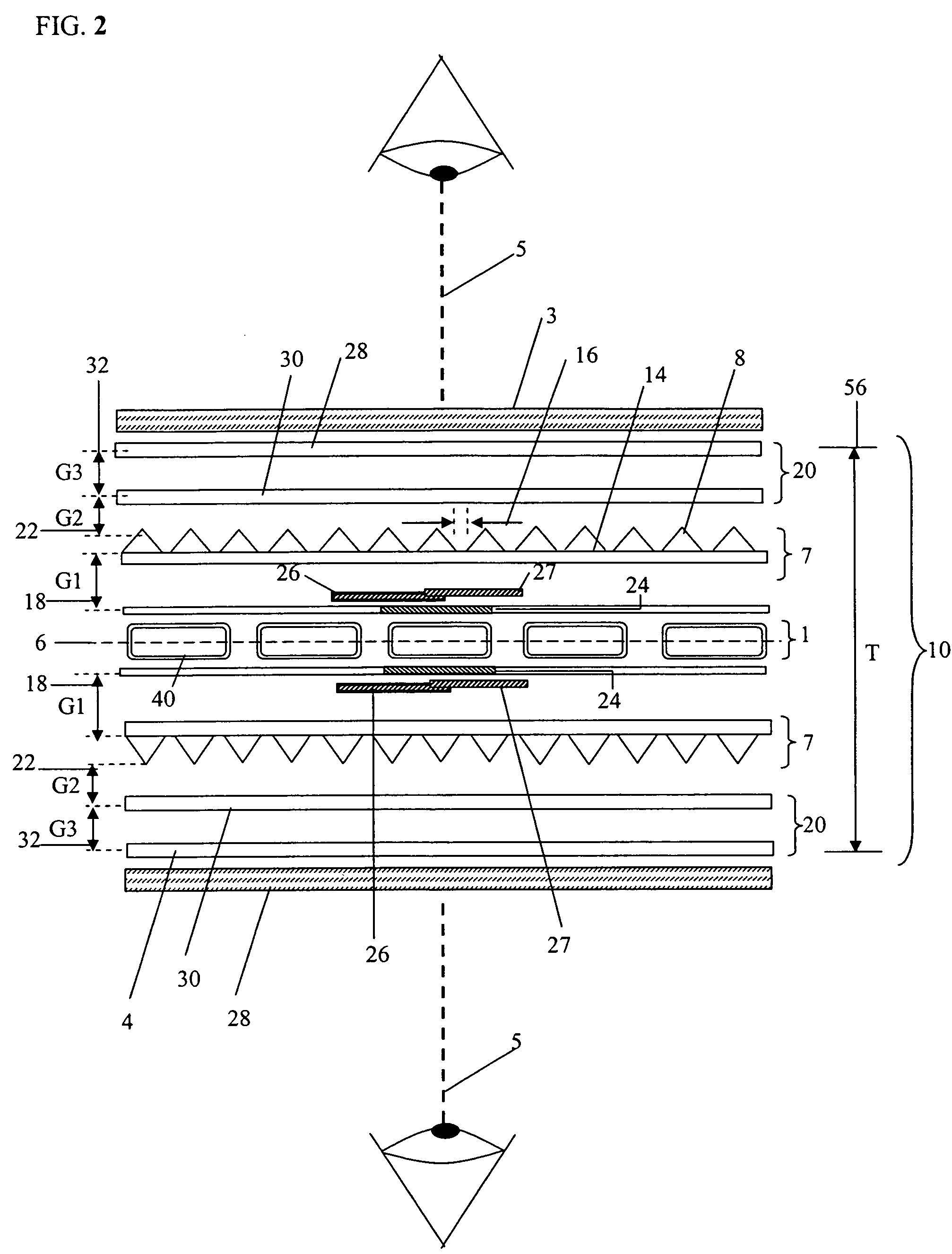
[0158]One form of the present invention involves the use of a stack of light directing layers disposed above a plane of separated emitters arranged either as an array of parallel stripes or as a two-dimensional array of bounded emitting regions such that a directed output beam of even uniformity is created as if from a continuous emitter of area equal to that to the output aperture. One (or two) of the light directing layers are prism sheets whose geometry and elevation above the plane of emitters is chosen uniquely so as to create the required overlap and diffusion of emitter images.

[0159]An optical system constructed in accordance with one principal form of the invention is indicated generally in FIG. 1 and represents a side elevation. The optical system 10 embodies a structure and method, which uses various optical elements, disposed in a compact geometry relative to an intrinsically discontinuous light source 1 formed by an array of emitters, and manipulates this light to genera...


PUM


Abstract

A compact and efficient optical illumination system featuring planar multi-layered LED light source arrays concentrating their polarized or un-polarized output within a limited angular range. The optical system manipulates light emitted by a planar light emitters such as electrically-interconnected LED chips. Each light emitting region in the array is surrounded by reflecting sidewalls whose output is processed by elevated prismatic films, polarization converting films, or both. The optical interaction between light emitters, reflecting sidewalls, and the elevated prismatic films create overlapping virtual images between emitting regions that contribute to the greater optical uniformity. Practical illumination applications of such uniform light source arrays include compact LCD or DMD video image projectors, as well as general lighting, automotive lighting, and LCD backlighting.

Description

CROSS-REFERENCE TO RELATED PATENT APPLICATIONS[0001]This application is a Non-Provisional of U.S. Application 60 / 340,453, filed Dec. 14, 2001, incorporated herein by reference in its entirety. This application is a continuation-in-part of 10 / 319,800, which was filed Dec. 13, 2002, incorporated herein by reference in its entirety.BACKGROUND OF THE INVENTION[0002]The present invention is concerned generally with a thin and compact multi-layered optical system and method for generating well-organized output illumination from a spatially discontinuous one or two-dimensional array of discrete emitters, the output light emanating from one (or opposing sides) of the multi-layered system, uniformly over the system's aperture. The field of illumination produced by the optical systems containing these emitting arrays is rendered visually featureless so as to provide useful rear-illumination for an image to be viewed directly, an illuminating beam for an image to be projected onto a screen, or...

Claims


Application Information

Patent Timeline
IPC IPC(8): G02B26/08F21V5/00F21V7/00F21V9/14G02B27/10G02B27/00G02B27/14G02B27/28G02F1/13357H01L25/075
CPCF21S8/08G02B6/0028G02B27/0994G02B27/1026G02B27/1033G02B27/1046G02B27/1053G02B27/1066G02B27/1073G02B27/123G02B27/126G02B27/145G02B27/147G02B27/149G02B27/283G02F1/133603G02F1/133604G02F1/133605H04N9/3105H04N9/315H04N9/3197G02B19/0066G02B19/0028F21W2101/10H01L2924/0002F21W2131/10F21W2131/406F21Y2101/02G02B5/045G02B6/0031G02B6/0043G02B6/0053H01L25/0753H01L2924/00F21Y2115/10F21S41/12F21S41/141F21Y2105/10F21W2102/00
Inventor HOLMAN, ROBERT L.
Owner SNAPTRACK
Why Eureka
Eureka Blog
Learn More