Alternating current rotatable sputter cathode

Inactive Publication Date: 2008-07-15
APPLIED MATERIALS INC
View PDF31 Cites 28 Cited by
  • Summary
  • Abstract
  • Description
  • Claims
  • Application Information

AI Technical Summary

Benefits of technology

[0019]In contrast to the prior art, the present invention provides a method and apparatus for minimizing or eliminating the induction heating in an oscillating current sputter process, and thus facilitates the more efficient sputtering of materials requiring high power density. Furthermore, an increase in sputter rate and sputter line speed of all sputter processes may be achieved by using the present invention with oscillating power. More specifically, the present invention relates to an oscillating powered cathode assembly which minimizes, if not eliminates, inductive heating in the rotary seal, main bearings and other cathode parts, and an oscillating power sputter method for accomplishing the same.
[0023]Another embodiment of the present invention may comprise a sputter chamber, one or more rotatable sputter cathodes with at least a portion of each of said cathodes positioned within said sputter chamber and a portion of said cathode disposed inside of a housing, and a rotary vacuum seal operably positioned between said cathode and said housing, means for supplying a current to the rotatably sputter cathode inside of the sputter chamber, thereby avoiding inductive heating of the vacuum seal.
[0028]A still further object of the present invention is to provide a method for sputtering in which the inductive heating of seals and other ferro-magnetic materials is substantially reduced or eliminated and which thereby facilitates the sputtering at high frequencies and currents.

Problems solved by technology

Particularly troublesome has been the development of suitable apparatus for driving and supporting the magnetron in the coating chamber.
However, such seals have a tendency to develop leaks under conditions of high temperature and high mechanical loading.
Another troublesome sputtering problem has been an arcing phenomena, which is particularly troublesome in the DC reactive sputtering of silicon dioxide and similar materials such as aluminum oxide and zirconium oxide.
In addition, when faster sputtering is desired, the power supplied must also be increased, resulting again in undesirable arcing.
Perturbation of the sputtering conditions due to arcing is especially detrimental to a cost effective operation, as any article being coated when an arc occurs will most likely be defective.
For instance, the article may be contaminated by debris resulting from the arc, or it may have an area with incorrect film thickness caused by temporary disruption of the discharge conditions.
Furthermore, the occurrence of arcs increases with operating time, and eventually reaches a level which requires that the system be shut down for cleaning and maintenance.
Utilizing a fluctuating electrical current, however, gives rise to other types of problems.
However, as frequency and / or current are increased, the rate of inductive heating becomes more and more significant and problematic.
Furthermore, to maintain the same power density over a long cathode requires more current, further exacerbating the heating problem.
The electrical induced heating effect is even more of a problem when ferro-fluid seals are used.
If the currency and frequency are high enough, the seal overheats and fails.
This failure is usually catastrophic to the sputtering process and thus costly to manufacturing.
Additionally, the inductive heating represents a waste of energy and thus reduced efficiency in the sputtering process.

Method used


Image

  • Alternating current rotatable sputter cathode
  • Alternating current rotatable sputter cathode
  • Alternating current rotatable sputter cathode

Examples


Embodiment Construction

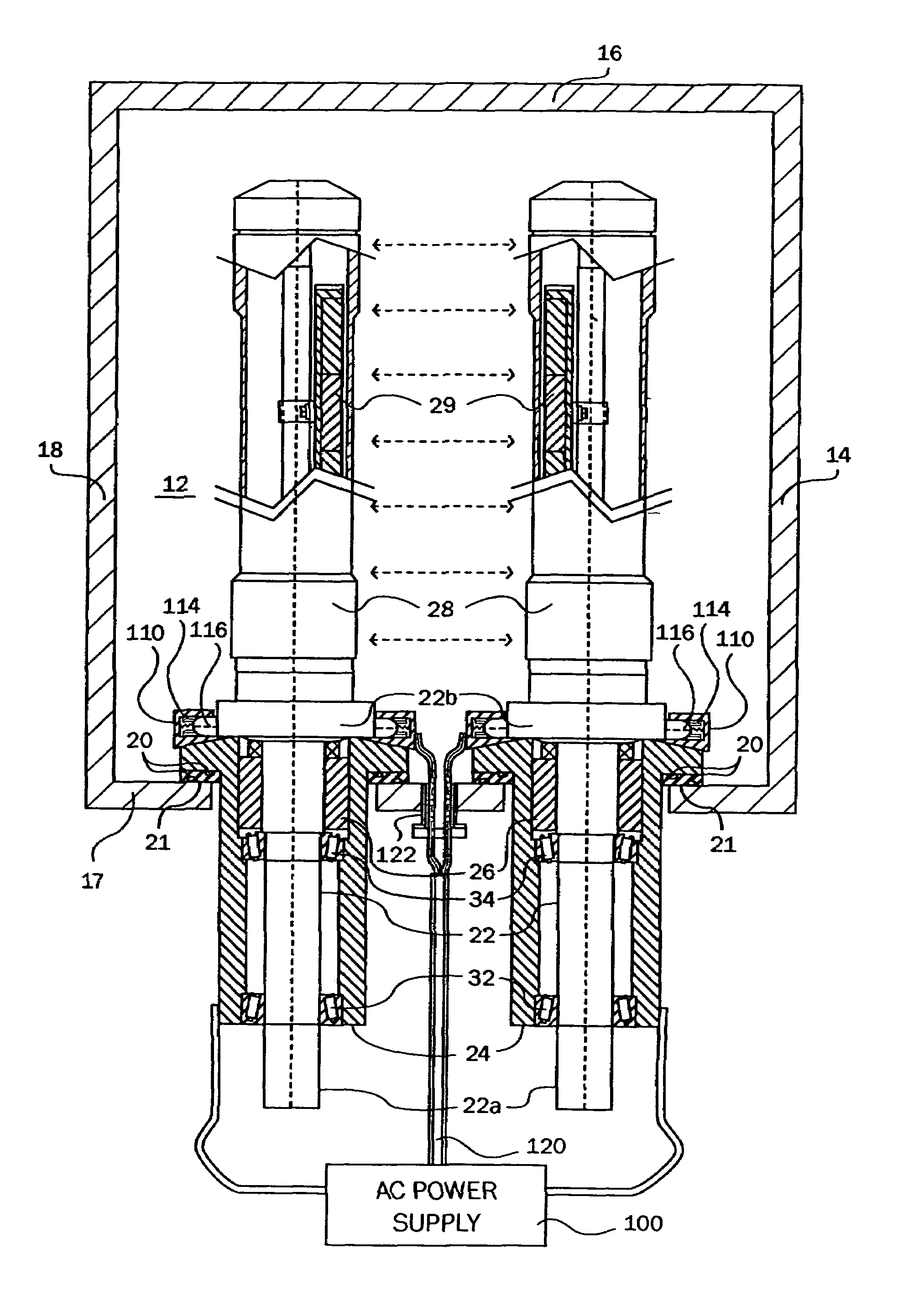
[0033]The present invention will be described in terms of a rotatable sputter cathode and more particularly a horizontally disposed cathode although this invention applies equally to vertically disposed cathodes. Further, the teachings of the present invention may be utilized in any type of sputter cathode, whether rotatable or not, that experiences current induced heating. Although the invention has application to cathodes using a DC power source, it has particular application to cathodes and sputtering processes driven by a fluctuating power source. This may include standard alternating current (AC), square or pulsed direct current and bipolar direct current, among others.

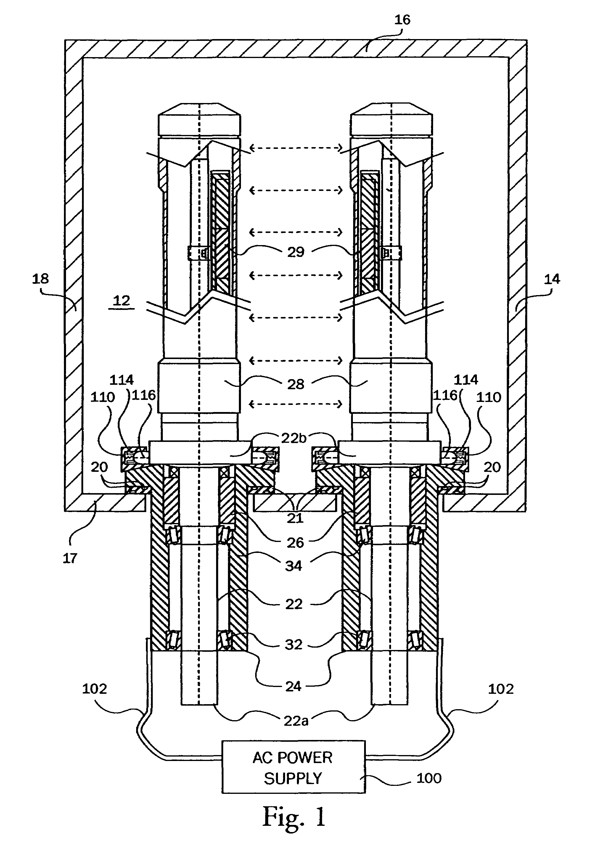
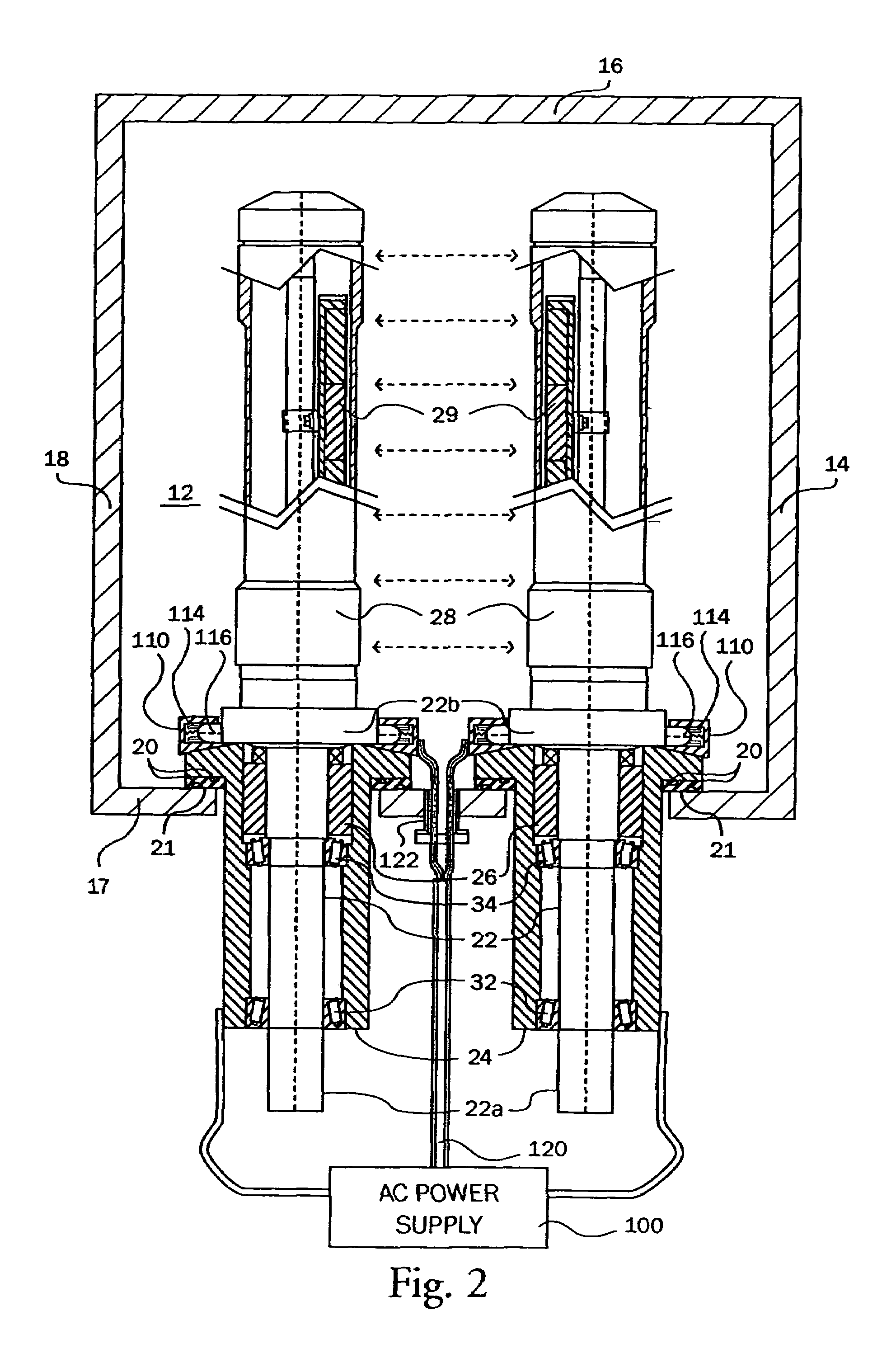
[0034]As shown in FIG. 1, the present embodiment is a cantilever mounting arrangement for a rotating sputter cathode 10 disposed in an evacuable coating or vacuum chamber 12. The coating chamber 12 may further comprise a floor 14, a side wall 16, a side wall 17, and a top wall 18 connected as illustrated in FIG. ...


PUM

PropertyMeasurementUnit
Electrical conductivityaaaaaaaaaa

Abstract

The present invention is an alternating current rotary sputter cathode in a vacuum chamber. The apparatus includes a housing containing a vacuum and a cathode disposed therein. A drive shaft is rotatably mounted in the bearing housing. A rotary vacuum seal is located in the bearing housing for sealing the drive shaft to the housing. An at least one electrical contact is disposed between a power source and the cathode for transmittal of an oscillating or fluctuating current to the cathode. The electrical contact between the power source and the cathode is disposed inside of the vacuum chamber, greatly reducing, and almost eliminating, the current induced heating of various bearing, seals, and other parts of the rotatably sputter cathode assembly.

Description

CROSS-REFERENCE TO RELATED APPLICATION[0001]This application is a continuation in part of U.S. patent application Ser. No. 09 / 881,555, filed on Jun. 14, 2001, now abandoned the contents of which is incorporated in its entirety by reference.BACKGROUND OF THE INVENTION[0002]1. Field of the Art[0003]The present invention relates generally to a sputter cathode assembly and more particularly to a high current rotating sputter cathode assembly in which the power is supplied to the cathode at a point within the sputter chamber.[0004]2. Description of the Prior Art[0005]Direct current (“DC”) reactive sputtering is often used for large area commercial coating applications, such as the application of thermal control coatings to architectural and automobile glazings. In this process, the articles to be coated are passed through a series of in-line vacuum chambers isolated from one another by vacuum locks. Such a system may be referred to as a continuous in-line system, or simply a glass coater...

Claims


Application Information

Patent Timeline
IPC IPC(8): C23C14/35H01J37/34
CPCH01J37/32577H01J37/3405H01J2237/166
Inventor GERMAN, JOHN R.CROWLEY, DANIEL T.MEINKE, BRIAN P.PETERSON, ROGER L.
Owner APPLIED MATERIALS INC
Why Eureka
Try Eureka