
Device for an axially slidable cable in a connector housing

a technology of axial sliding and connector housing, which is applied in the direction of coupling device connection, engagement/disengagement of coupling parts, electrical apparatus, etc., can solve the problem of relative movement between the contact and the contact latching mechanism no longer being possible, and achieve the effect of high extraction for

Active Publication Date: 2008-07-15
HARTING ELECTRIC GMBH & CO KG
View PDF1 Cites 15 Cited by
  • Summary
  • Abstract
  • Description
  • Claims
  • Application Information

AI Technical Summary

Benefits of technology

[0013]The two guide rails are simultaneously guided in corresponding guide grooves in the collar of the connector housing and advantageously prevent the sliding sleeve from being turned relative to the connector housing. An electric cable fixed within the sliding sleeve by means of a strain relief and a gland nut can be displaced relative to the connector housing by the predetermined distance, wherein a connector enclosure that provides an advantageous seal relative to the environment is formed due to the sealing effect of the circumferential gasket on the collar of the connector housing and the sliding sleeve, and wherein the high extraction forces for the electric cable are simultaneously preserved.

Problems solved by technology

However, if a higher degree of protection with a housing that provides additional protection and features its own latching mechanism and with a sealing contour is required, a relative movement between the contact and the contact latching mechanism is no longer possible.

Method used


Image

  • Device for an axially slidable cable in a connector housing
  • Device for an axially slidable cable in a connector housing
  • Device for an axially slidable cable in a connector housing

Examples


Embodiment Construction

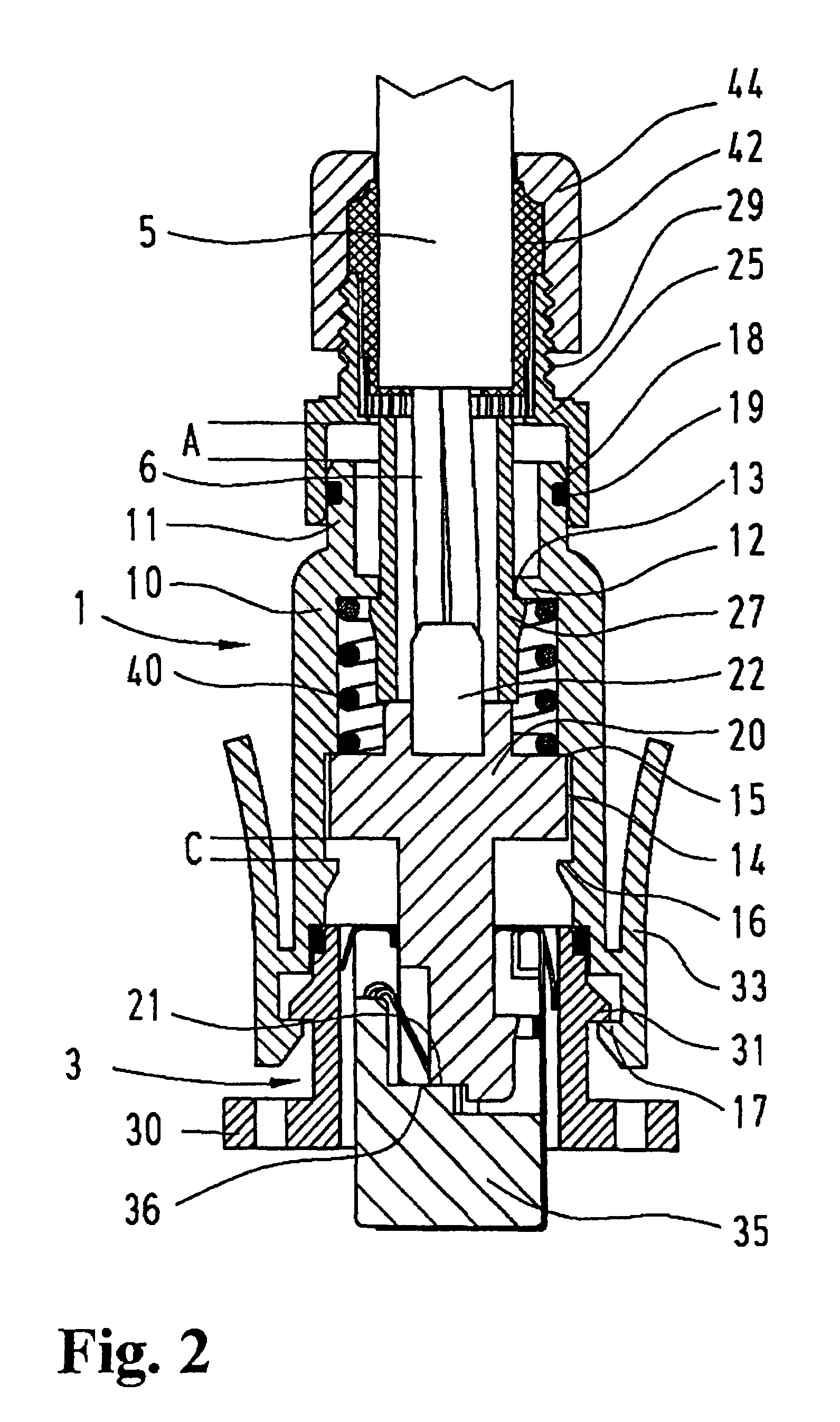
[0019]FIG. 1 shows a section through a connector 1 with a connector housing 10 that features a device for axially or slidably displacing an electric cable 5.

[0020]The mating side of the connector housing 10 is provided with integral latching elements for fixing the connector housing on a female connector.

[0021]A sliding sleeve 25 is slipped on a collar 11 of the connector housing 10 on the cable side. Several locking devices 26 are integrally moulded onto the sliding sleeve and extend into the connector housing 10 through an opening 13. Quick-release hooks 27 are provided on at least two locking devices and serve for holding the sliding sleeve on the rear panel 12 of the connector housing in a captive fashion. In this case, the hooks are arranged such that the sliding sleeve can be axially displaced relative to the connector housing by a certain distance C.

[0022]The contact holder 20 with a part 22 integrally moulded thereon is inserted between the locking devices. The contact holde...


PUM


Abstract

In order to realize a connector housing (10) that is tightly sealed relative to the environment, there is provided a device for an axially slidable connector-ended cable (5) because a contact holder (20) connected to the connector-ended cable can be displaced by a defined axial distance (C) within the connector housing, wherein a constant pressure is exerted upon the contact holder (35) of a corresponding female connector (3) by means of an integrated pressure spring (40).

Description

BACKGROUND OF THE INVENTION[0001]1. Field of the Invention[0002]The invention pertains to a device for a contact holder with a connector-ended cable that is arranged within a connector housing in an axially slidable fashion.[0003]A connector housing of this type is required in order to also utilize connectors with their own contact latching mechanisms in an industrial environment.[0004]2. Description of the Related Art[0005]There exist numerous connectors that feature a latching mechanism arranged for a definite overlapping contact area or to compensate tolerances between the contacts.[0006]These latching mechanisms secure the end position in the mated state. When the connection is produced, the contact pairs are joined and the connectors are held against one another by pressure springs. The latching is achieved with displaceable holding means in this case. The housing of the connector carries out a movement relative to the contact and therefore the connected cable.[0007]This displa...

Claims


Application Information

Patent Timeline
Patent Type & Authority Patents(United States)
IPC IPC(8): H01R13/62
CPCH01R13/6315H01R13/6273
Inventor SCHMIDT, MARTIN
Owner HARTING ELECTRIC GMBH & CO KG
Learn More