
Skylight

a technology of skylights and domes, applied in the field of skylights, can solve the problems of reducing reducing the ability of dome skylights to be inserted into the roofs of buildings, and affecting the performance of skylights, so as to reduce the light transmittance of skylights, improve the effect of skylights, and increase the cost of their manufactur

Inactive Publication Date: 2008-07-08
ABL IP HLDG
View PDF68 Cites 75 Cited by
  • Summary
  • Abstract
  • Description
  • Claims
  • Application Information

AI Technical Summary

Benefits of technology

[0012]Dome skylights inserted into the roofs of buildings are often exposed to harsh elements such as hail and heavy snow. Such skylights also pose a significant safety risk to those persons performing maintenance or other tasks on those roofs. As a result, dome skylights are commonly composed of light-transmitting material that is quite thick or provided with protective bars surrounding or inserted into the skylights. These additional features diminish the light transmittance of the skylights and increase the cost of their manufacture.
[0013]The present invention, however, provides for an improved skylight. The surface area of the skylight is increased by having corrugations disposed on an arched main body. This arched and corrugated structure increases the strength of the skylight. This structure also permits the skylight to be made with thinner material than conventional skylights, thereby providing for more efficient heat transfer. The skylight also has two end portions that are angled toward the midline of the main body. These end portions have the ability to collect light that originates from light sources nearly perpendicular relative to the base of the skylight. Additionally, these end portions and corrugations are angled so as to increase the angle of incidence of the light striking their surfaces. This increased angle of incidence results in a high angle of reflection and, consequently, little light is reflected off those surfaces. In sum, the present invention overcomes the shortcomings of the prior art.

Problems solved by technology

This minimal surface area limits the ability of domed surface 802 to collect sunlight and dissipate heat.
Dome skylights inserted into the roofs of buildings are often exposed to harsh elements such as hail and heavy snow.
Such skylights also pose a significant safety risk to those persons performing maintenance or other tasks on those roofs.
These additional features diminish the light transmittance of the skylights and increase the cost of their manufacture.

Method used


Image

  • Skylight
  • Skylight
  • Skylight

Examples


Embodiment Construction

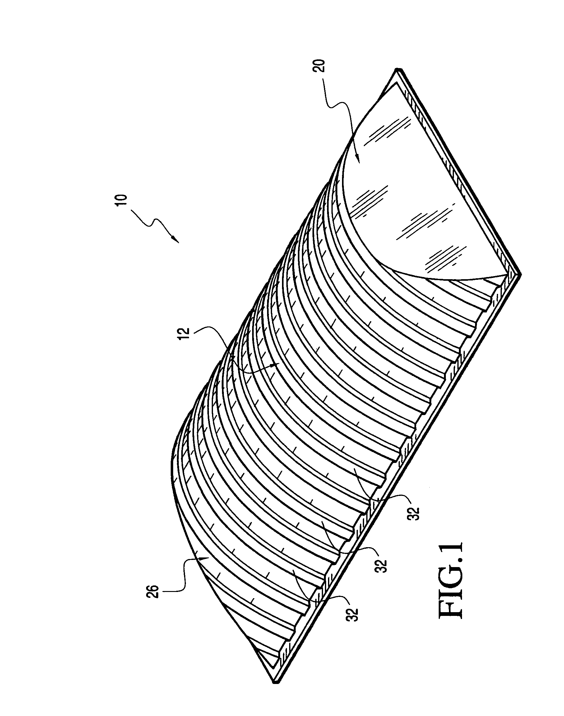
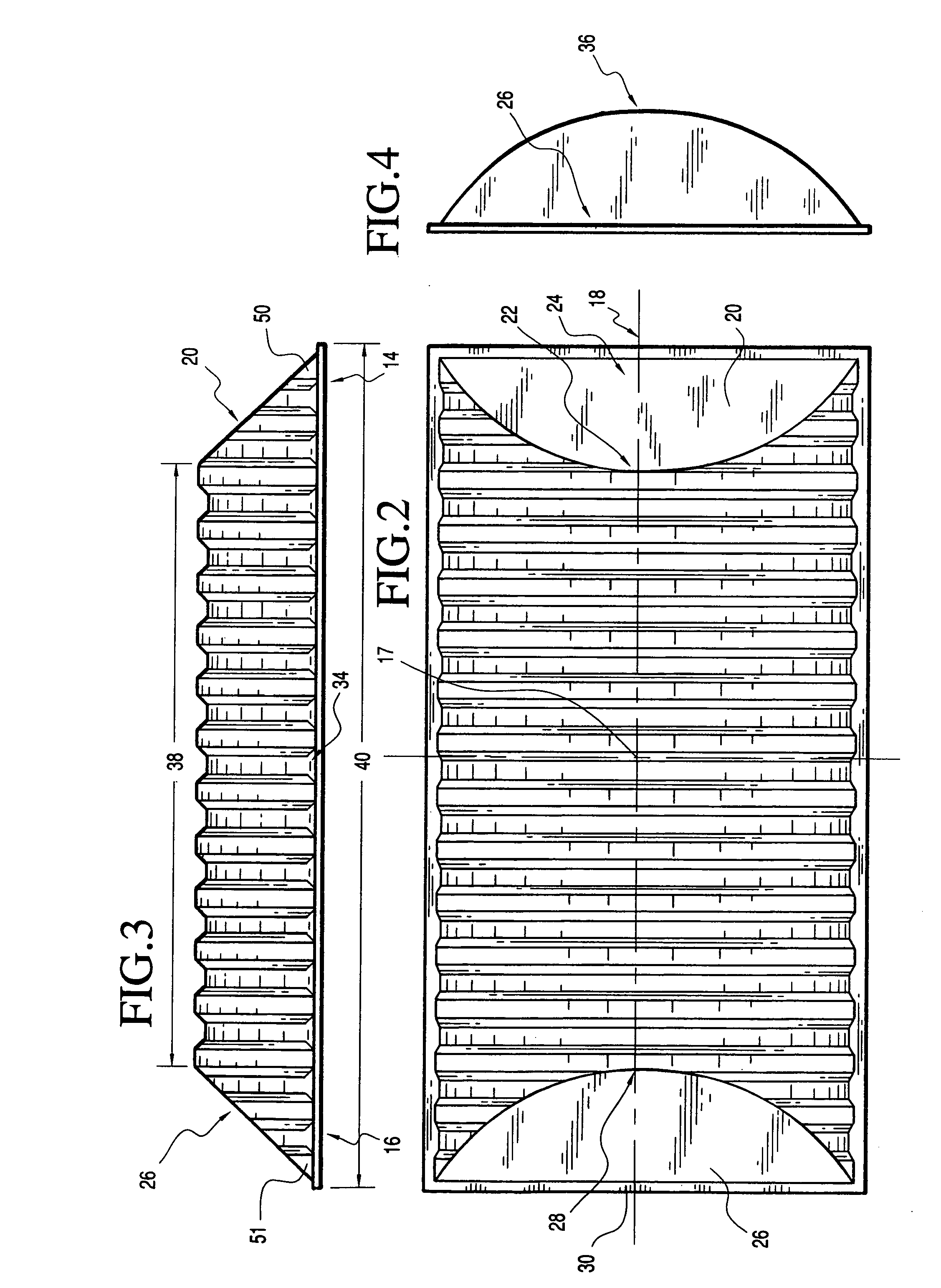
[0042]FIGS. 1-5, as well as FIGS. 21 and 22, show an exemplary embodiment of a skylight 10 made in accordance with this invention. Skylight 10 includes a main body 12, a first end portion 20, a second end portion 26, and corrugations 32.

[0043]Main body 12 is arched and has a base 34 and an apex 36. Main body 12 is arched along its longitudinal axis 18. It should be appreciated that in other exemplary embodiments the main body is arched along an axis substantially perpendicular to its longitudinal axis. Main body 12 is arched in the shape of a curve. It is preferred that main body 12 be arched in the shape of a parabola. In other various exemplary embodiments of the invention, the main body is arched in other shapes, such as, for example an A-frame shape or in a continues curve. Main body 12 arches from base 34 and reaches its maximum height at apex 36.

[0044]Main body 12 further includes a first length 38 and a second length 40. It should be appreciated that the main body is comprise...


PUM


Abstract

A skylight having an arched main body, an apex, a base, and corrugations is described. The main body has two lengths, the first being at substantially the apex and the second at the base wherein the first length is less than the second length. The skylight also has a first end portion and a second end portion at opposing ends of the main body, each of which has a top and bottom section. The distance between the top sections define the first length and the distance between the bottom sections defines the second length. The corrugations disposed on the main body vary by orientation, method of manufacture, number, and shape.

Description

CROSS REFERENCE TO RELATED APPLICATIONS[0001]This application claims the benefit of provisional application number 60 / 396,193 which was filed on Jul. 15, 2002 and which is incorporated herein by reference.BACKGROUND OF THE INVENTION[0002]1. Field of the Invention[0003]The present invention relates to the field of skylights.[0004]2. Description of Related Art[0005]Conventional skylights are typically made of light-transmitting plastic or glass, and have either a planar, tubular, pyramidal, or domed shape.[0006]Skylights are commonly inserted into the roofs of buildings to introduce natural light into the interior of buildings to offset the need for artificial light. Another use for skylights is to permit heat to escape the building.[0007]An example of a typical skylight is a dome-shaped skylight having a 10% rise. Other examples are planar skylights, essentially horizontal windows that may or may not open, and tubular skylights that reflect light down through their tubes and into the...

Claims


Application Information

Patent Timeline
IPC IPC(8): E04D13/03
CPCE04D13/03
Inventor BLOMBERG, JEROME
Owner ABL IP HLDG
Learn More