
Color correcting polarizer

a technology of color correction and polarizer, which is applied in the direction of polarising elements, instruments, non-linear optics, etc., can solve the problems of perceptual significant color errors and perceptual coloration of the polarizer, and achieve the effects of high photopic transmittance, effective, and preservation of luminance throughpu

Inactive Publication Date: 2006-12-05
NITTO DENKO CORP
View PDF29 Cites 38 Cited by
  • Summary
  • Abstract
  • Description
  • Claims
  • Application Information

AI Technical Summary

Benefits of technology

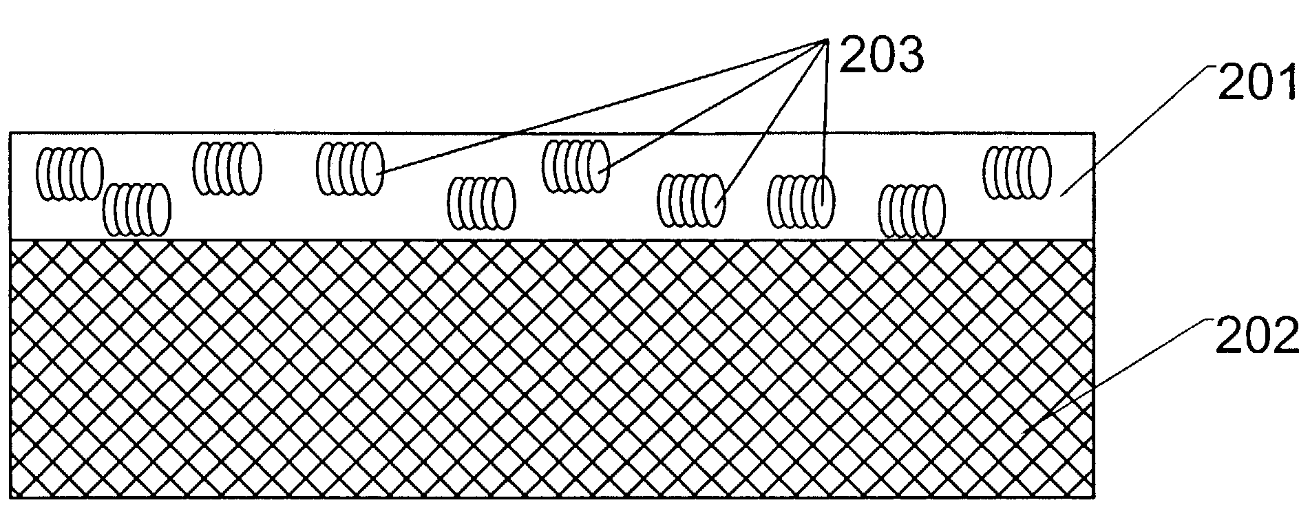
[0044]One advantage of the present invention is the preservation of luminance throughput of the liquid crystal cell or the polarizer that is color corrected. The discotic film layer of the present invention has high photopic transmittance, i.e. the spectral light transmittance weighted by the photopic sensitivity of the eye. The addition of the discotic film layer to the polarizer or liquid crystal cell, while providing effective color correction, accomplishes this function with only a minimal decrease in photopic transmittance. The typical decrease is in the range of 3 to 5%, which is negligible for most applications.
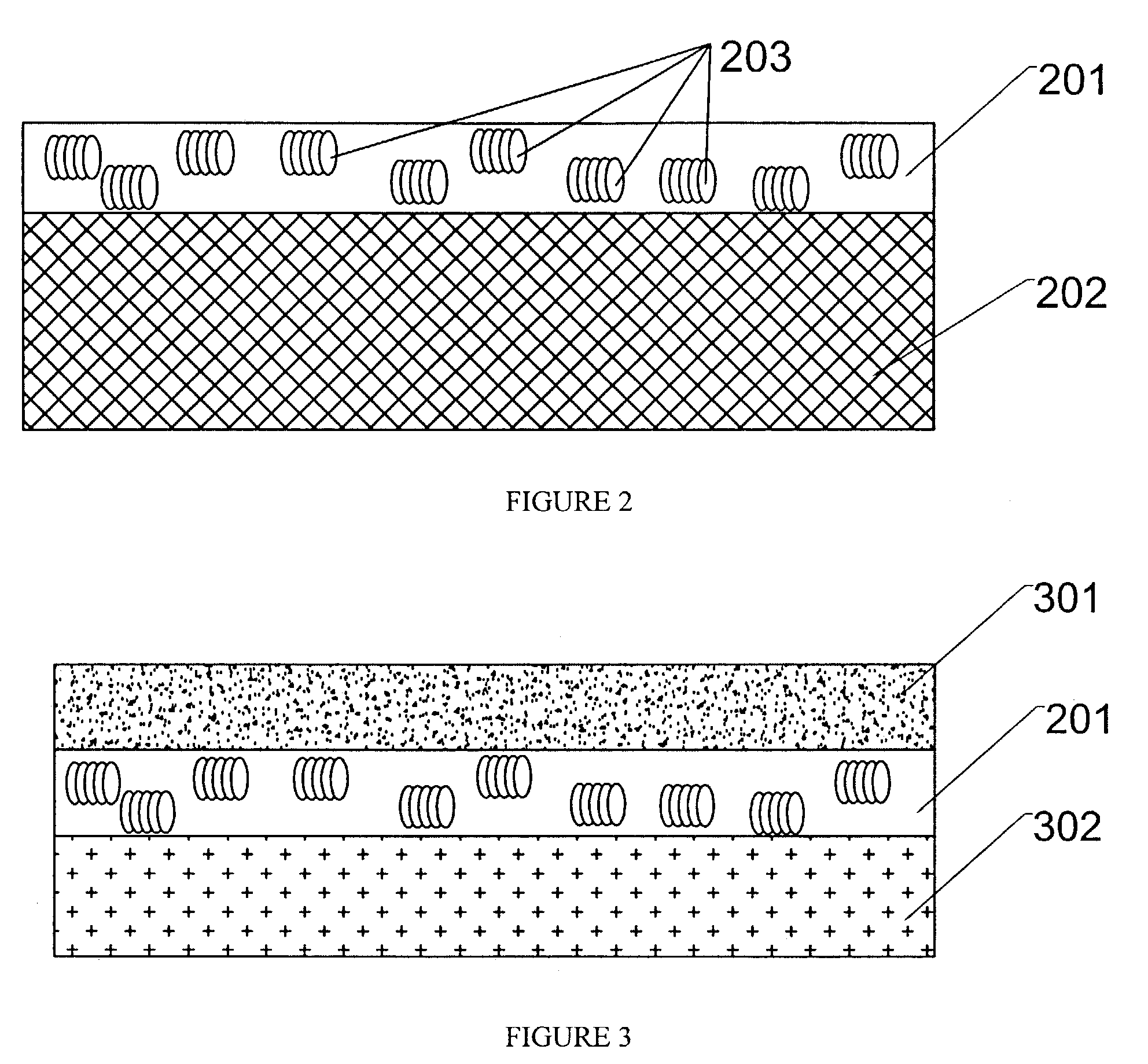
[0045]The use of the discotic film layer is possible with any polarizer or liquid crystal cell which relies on light polarization and includes integral polarizers. The discotic film layer can be deposited directly onto either front or rear panels of a liquid crystal cell, or onto any polarizer. This is another advantage of the present invention.
[0046]In addition to the method of manufacturing the color-correcting polarizer film and / or the liquid crystal cells with the color-correcting polarizer layer, the present invention also allows preparation of the polarizer with the discotic film layer attached to it before further manufacturing steps. This approach does not require any changes to the conventional manufacturing process for liquid crystal displays.
[0047]In the design with two discotic film layers placed inside or outside of the liquid crystal cell, the discotic film with the transmission axis parallel to the analyzer provides color correction for the black state and low gray levels, and the discotic film with the transmission axis perpendicular to the analyzer provides color correction for the white state and high gray levels.
[0048]There are also some other options in case the discotic film layer is positioned inside the liquid crystal cell. Then the transmission axis can be positioned at a certain angle with respect to the analyzer. This allows the discotic film to additionally function as an optical retarder. The angle between the transmission axes of the discotic film and the analyzer will be defined by the retardation characteristics of the discotic film layer and the desired amount of compensatory optical retardation for a particular application.
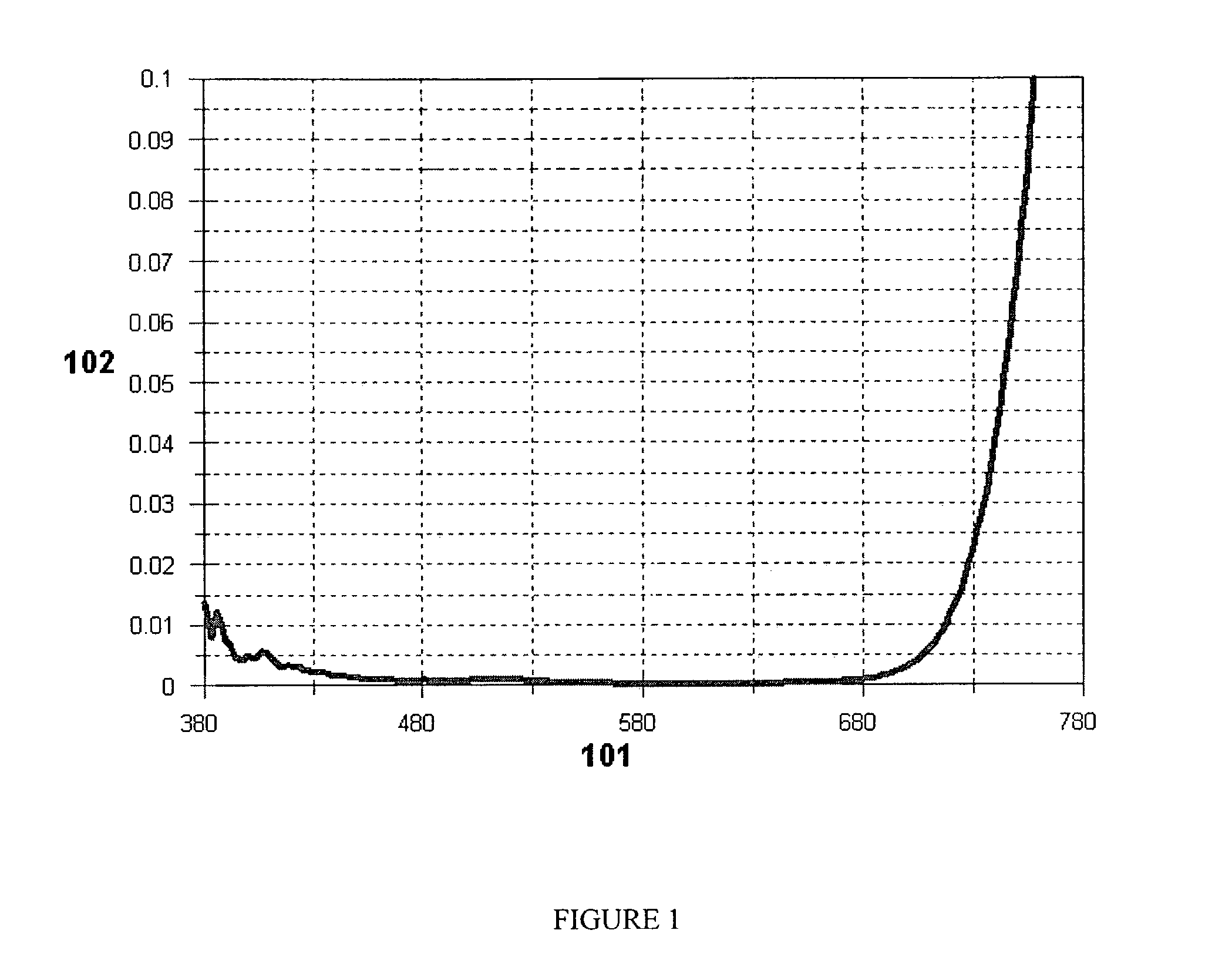
[0049]In one embodiment of the present invention, the discotic film layer has an absorption peak between 380 and 500 nm. In another embodiment, the discotic film layer has an absorption peak between 600 and 780 nm. The absorption peak in one of the described regions corrects the color gamut of the polarizer layer or the liquid crystal cell.

Problems solved by technology

Most liquid crystal displays suffer from perceptually significant color errors.
These leakages result in perceptible coloration of the polarizer.

Method used


Image

  • Color correcting polarizer
  • Color correcting polarizer
  • Color correcting polarizer

Examples


example 1

[0080]The technical advantages provided by the present invention were investigated using two active-matrix liquid crystal displays. The first display as shown in FIG. 7 was not color corrected and taken as reference point for comparison. The second display as shown in FIG. 8 was color corrected to demonstrate the results obtained by the present invention. FIGS. 9 to 12 show the obtained results.

[0081]FIG. 7 shows the structure of the reference liquid crystal display without the color correcting polarizer of the present invention. The basic design parameters of this configuration are as follows: (1) high-efficiency Nitto G-1224-DU sheet polarizers (701, 707) with transmission axes aligned at 45° at the rear of the liquid crystal cell (707) and at −45° at the front analyzer (701) location; (2) a 90° clockwise twist in the liquid crystal layer (706) from −45° at the rear substrate to −135° degrees at the front substrate, such that the alignment of the rubbing directions in combination ...


PUM


Abstract

A color-correcting polarizer is provided comprising a polarizer layer and at least one discotic film layer. The discotic film layer is optically transparent within the range of visible wavelength. The discotic film layer works as a polarizer in the wavelength ranges at least from 380 to 500 nm and / or from 600 to 780 nm. A liquid crystal cell comprising the color correcting polarizer is also disclosed.

Description

RELATED APPLICATIONS[0001]This application claims priority to U.S. Provisional Application No. 60 / 442,440 filed Jan. 24, 2003, the disclosure of which is hereby incorporated by reference in its entirety.FIELD OF THE INVENTION[0002]This invention relates in general to liquid crystal displays, and in particular to liquid crystal displays having color-correction polarizers.BACKGROUND OF THE INVENTION[0003]Most liquid crystal displays suffer from perceptually significant color errors. The spectral selectivity of liquid crystal layers is one of the origins responsible for wrong color rendering and grayscale coloring in liquid crystal displays.[0004]The operation principle of a liquid crystal display requires a polarizer. The function of the polarizer is to selectively transmit or reflect light with a preferred direction of polarization. The unpolarized light transmitted through (or reflected by) linear polarizer has a polarization direction collinear with the so-called transmission axis ...

Claims


Application Information

Patent Timeline
IPC IPC(8): G02F1/01C09K19/34C09K19/60G02B5/30G02F1/1335
CPCC09K19/3452C09K19/60G02F1/133528G02B5/3016Y10T428/1041C09K2323/031G02B5/30
Inventor PAUKSHTO, MICHAEL V.SILVERSTEIN, LOUIS D.
Owner NITTO DENKO CORP
Learn More