
Method of wide azimuth seismic acquisition

a seismic acquisition and wide azimuth technology, applied in seismology, seismology, instruments, etc., can solve the problems of false prospecting, false prospecting, and/or failure to drill, and the quality of the image of the subsurface ultimately is limited,

Inactive Publication Date: 2008-06-24
BP CORP NORTH AMERICA INC
View PDF15 Cites 69 Cited by
  • Summary
  • Abstract
  • Description
  • Claims
  • Application Information

AI Technical Summary

Benefits of technology

This approach improves the imaging quality of subsurface structures by collecting seismic data from a wider range of azimuths, reducing the likelihood of under-imaged regions and artifacts, and providing a more accurate representation of the subsurface, thereby aiding in the identification of hydrocarbon-bearing structures.

Problems solved by technology

However, for all of the advances that have been made in recent years in the technology of seismic processing, the resulting image of the subsurface is ultimately limited by the quality of the seismic data that is collected in the field.
For all of its usefulness, conventionally acquired marine seismic data have been shown to be a less than perfect means of exploring for hydrocarbon reserves when such are located beneath complex structures such as salt domes.
One important consequence of collecting data that illuminates the subsurface over a limited range of angles is that the resulting seismic volumes and sections will potentially be imperfect representations of the subsurface, and, thus, may cause false prospects to be drilled and / or promising targets to be missed.

Method used


Image

  • Method of wide azimuth seismic acquisition
  • Method of wide azimuth seismic acquisition
  • Method of wide azimuth seismic acquisition

Examples


Embodiment Construction

[0030]While this invention is susceptible of embodiment in many different forms, there is shown in the drawings, and will herein be described hereinafter in detail, some specific embodiments of the instant invention. It should be understood, however, that the present disclosure is to be considered an exemplification of the principles of the invention and is not intended to limit the invention to the specific embodiments or algorithms so described.

GENERAL ENVIRONMENT OF THE INVENTION

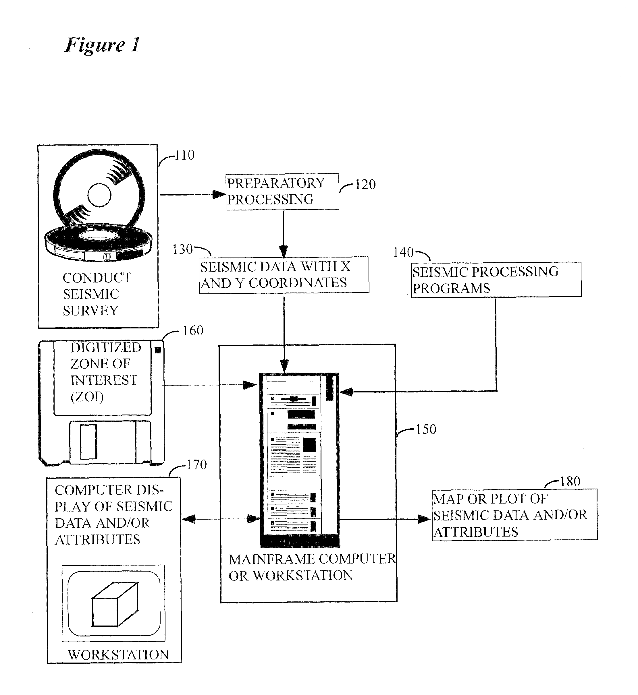
[0031]FIG. 1 illustrates the general environment in which the instant invention would typically be used. Seismic data 110 are collected in the field over a subsurface target of potential economic importance and are typically sent thereafter to a processing center. Seismic surveys might be conducted on either land or water, but for purposes of the instant invention marine acquisition only will be considered. It should be noted that the instant invention would typically be utilized during step 110 of this f...


PUM


Abstract

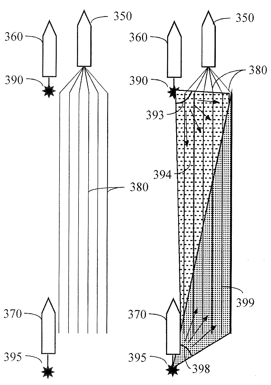
According to a preferred aspect of the instant invention, there is provided a system and method for acquiring seismic data in a marine environment, wherein at least two source vessels are used in conjunction with a recording vessel which tows a plurality of hydrophone cables. Preferably, the source vessels will be positioned along side of the towed streamer configuration and most preferably one source vessel will be located near the recording vessel and the other at the end of the streamer configuration, preferably along the same side of the streamer configuration as the lead source vessel.

Description

CROSS REFERENCE TO RELATED CASES[0001]This application claims the benefit of U.S. Provisional Patent Application Ser. No. 60 / 749,681 filed on Dec. 12, 2005 and incorporates said provisional application by reference into this disclosure as if fully set out at this point.TECHNICAL FIELD[0002]This invention relates to the general subject of seismic exploration and, in particular, to methods for quantifying and visualizing complex subsurface structures with seismic data.BACKGROUND OF THE INVENTION[0003]A seismic survey represents an attempt to image or map the subsurface of the earth by sending sound energy down into the ground and recording the “echoes” that return from the rock layers below. The source of the down-going sound energy might come, for example, from explosions or seismic vibrators on land, or air guns in marine environments. During a seismic survey, the energy source is placed at various locations near the surface of the earth above a geologic structure of interest. Each ...

Claims


Application Information

Patent Timeline
Patent Type & Authority Patents(United States)
IPC IPC(8): G01V1/00G01V1/38
CPCG01V1/3808G01V2210/165
Inventor REGONE, CARLMICHELL, SCOTT T.ETGEN, JOHN T.THREADGOLD, IAN
Owner BP CORP NORTH AMERICA INC
Learn More