
Correction of motion measurement errors beyond the range resolution of a synthetic aperture radar

a technology of synthetic aperture and motion measurement error, applied in the field of synthetic aperture radar, can solve the problems of large relative motion measurement error, large motion measurement error, and rendering the image useless

Active Publication Date: 2008-06-24
NAT TECH & ENG SOLUTIONS OF SANDIA LLC
View PDF5 Cites 37 Cited by
  • Summary
  • Abstract
  • Description
  • Claims
  • Application Information

AI Technical Summary

Problems solved by technology

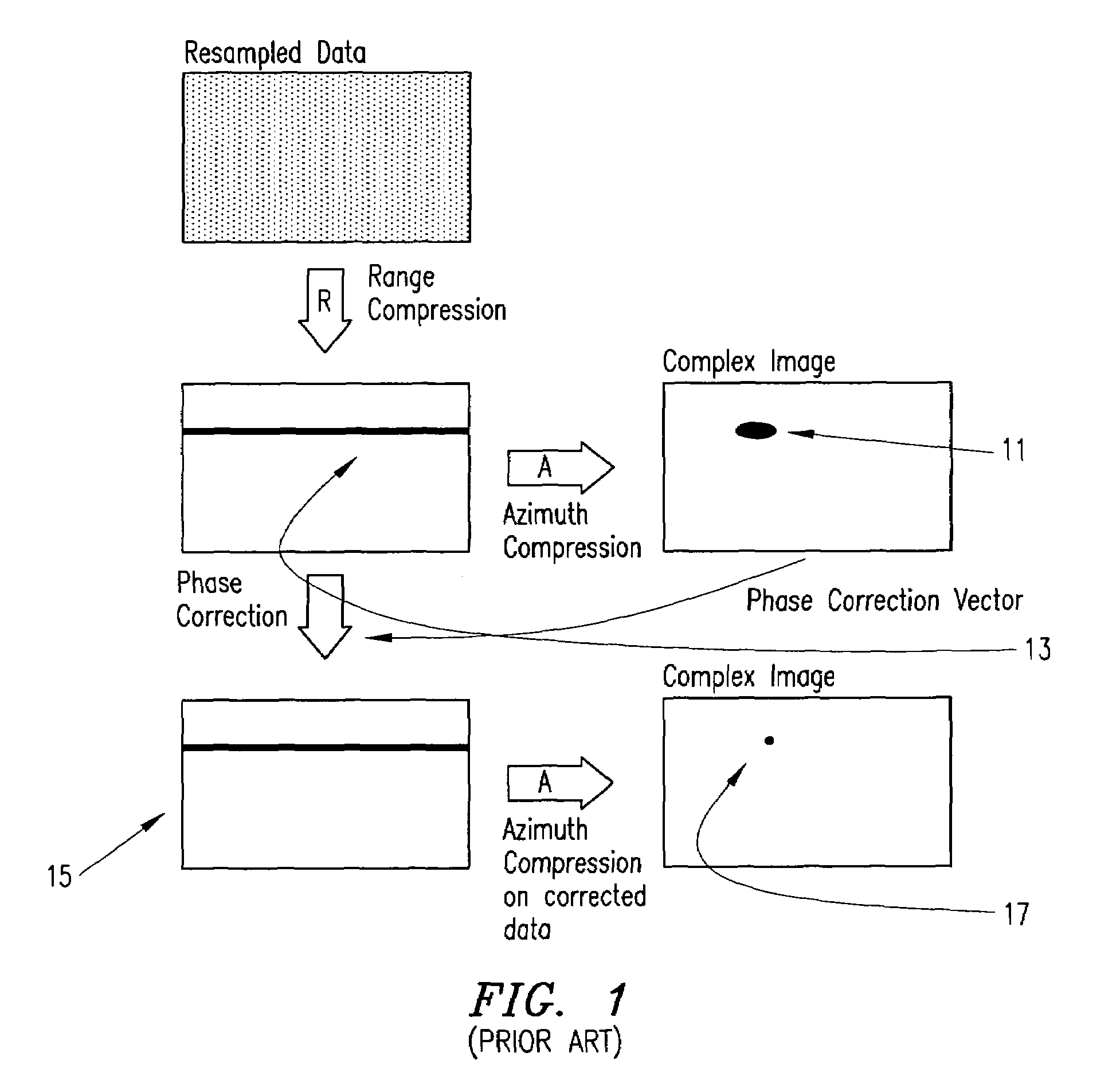
Relatively small motion measurement errors manifest themselves principally as phase errors in the complex data samples, and if large enough become observable as a smearing, blurring, or other degradation in the image.
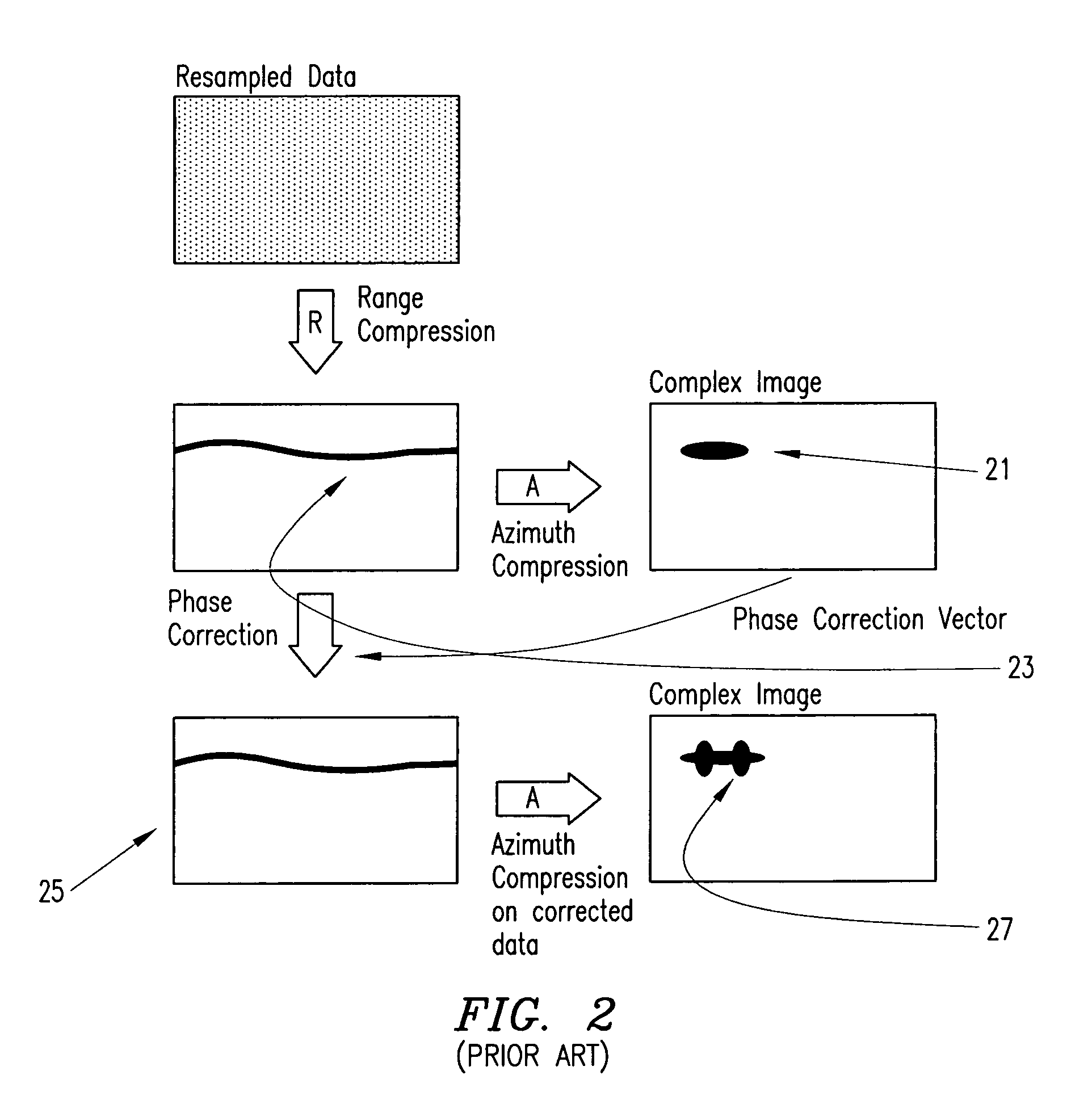
Very large relative motion measurement errors manifest themselves as an unexpected additional shifting or migration of target locations beyond the aforementioned deterministic migration during the course of the synthetic aperture.
Degradation in images from data exhibiting errors of this magnitude are substantial, often rendering the image useless.
Application of conventional autofocus techniques are unable to properly mitigate the image degradation.
In addition to motion measurement errors, longer ranges impart greater deleterious atmospheric effects to the data, whereby electrical path lengths depart significantly from the physical path lengths.
Since coherence depends on electrical path lengths, problematic errors similar to motion measurement errors may be induced by perturbations in the atmosphere's transmission characteristics in spite of perhaps otherwise adequate motion measurements.
The drive for finer resolutions, longer ranges, and less expensive (and less accurate) motion measurement systems will increasingly cause situations where a target's echo return effectively exhibits a residual migration error exceeding one or more range resolution cells during the course of the synthetic aperture.
This would doom to failure any autofocus scheme that presupposes otherwise, which includes autofocus schemes that operate only on fully range-compressed data.

Method used


Image

  • Correction of motion measurement errors beyond the range resolution of a synthetic aperture radar
  • Correction of motion measurement errors beyond the range resolution of a synthetic aperture radar
  • Correction of motion measurement errors beyond the range resolution of a synthetic aperture radar

Examples


Embodiment Construction

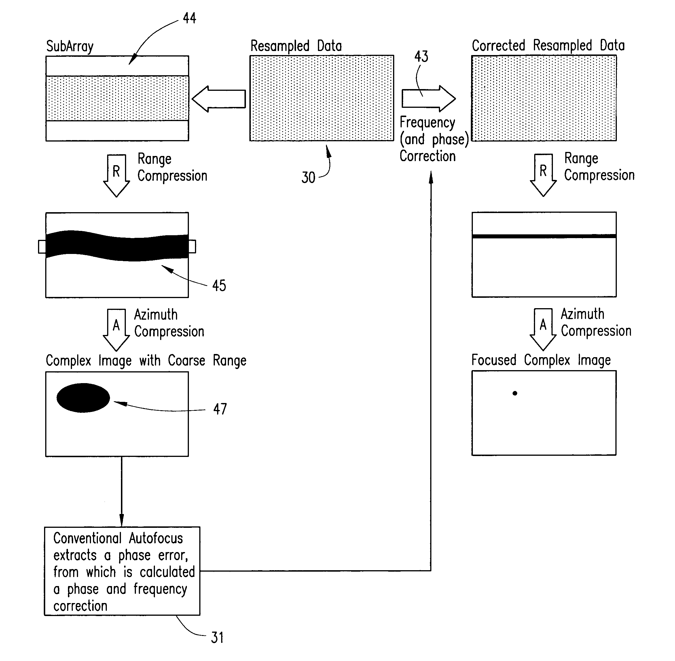
[0027]The present invention recognizes that a phase error function in the azimuth direction cannot be ascertained from a fully range-compressed data set, since the error energy is spread across several range resolution widths. Therefore, some embodiments impose the constraint that, for extracting an autofocus correction vector, the range resolution must be coarse enough to encompass the phase error. Put another way, the phase error is measured on data that is not fully range-compressed, i.e. radar data with degraded range resolution. This can be done in some embodiments by using only part of each return echo, that is, a portion of the fast-time vector. It can also be done in some embodiments by blurring fully range-compressed data in the range dimension. In embodiments that use range subapertures for image formation, a single range subaperture can be employed for phase-error measurement. Once an accurate phase error has been measured, then the corresponding migration effects can be ...


PUM


Abstract

Motion measurement errors that extend beyond the range resolution of a synthetic aperture radar (SAR) can be corrected by effectively decreasing the range resolution of the SAR in order to permit measurement of the error. Range profiles can be compared across the slow-time dimension of the input data in order to estimate the error. Once the error has been determined, appropriate frequency and phase correction can be applied to the uncompressed input data, after which range and azimuth compression can be performed to produce a desired SAR image.

Description

CROSS-REFERENCE TO RELATED APPLICATIONS[0001]This application claims the priority under 35 U.S.C. §119(e)(1) of co-pending provisional application Ser. No. 60 / 665,318 filed Mar. 25, 2005 and incorporated herein by reference.STATEMENT REGARDING FEDERALLY SPONSORED RESEARCH OR DEVELOPMENT[0002]This invention was developed under Contract DE-AC04-94AL8500 between Sandia Corporation and the U.S. Department of Energy. The U.S. Government has certain rights in this invention.FIELD OF THE INVENTION[0003]The invention relates generally to synthetic aperture radar (SAR) and, more particularly, to correction of motion measurement errors in SAR images.BACKGROUND OF THE INVENTION[0004]The documents listed below are incorporated herein by reference:[0005][1] J. L. Walker, “Range-Doppler Imaging of Rotating Objects,” IEEE Trans. on Aerospace and Electronic Systems, AES-16 (1), 23-52, (1980).[0006][2] D. E. Wahl, P. H. Eichel, D. C. Ghiglia, C. V. Jakowatz Jr., “Phase Gradient Autofocus—A Robust To...

Claims


Application Information

Patent Timeline
Patent Type & Authority Patents(United States)
IPC IPC(8): G01S13/90
CPCG01S7/295G01S13/9035G01S13/9019G01S13/904
Inventor DOERRY, ARMIN W.HEARD, FREDDIE E.CORDARO, J. THOMAS
Owner NAT TECH & ENG SOLUTIONS OF SANDIA LLC
Learn More