
Dynamic communication channel allocation method and system

a communication channel and dynamic technology, applied in the field of fully distributed methods, can solve problems such as equipment faults, and achieve the effect of reducing costs and increasing data transfer flexibility

Inactive Publication Date: 2008-06-17
MONTGOMERY JR CHARLES D
View PDF18 Cites 11 Cited by
  • Summary
  • Abstract
  • Description
  • Claims
  • Application Information

AI Technical Summary

Benefits of technology

[0057](1) To increase the capability of supporting multi-channel communications mediums, such as WDM, DWDM, and U-DWDM (ultra-DWDM).
[0073]2. circuit switched transmission, where many data packets are multiplexed onto the same underlying circuit (or virtual circuit, or sub-rate multiplexed circuit).The first class of methods can provide users and operators the comfort of familiarity (since the information is converted into electronic domain at each hop for possible processing, monitoring, etc.). However, OEO conversion itself can be a bottleneck, requiring very costly high-speed elements, a large footprint, high energy consumption, special air conditioning, etc. Methods belonging to the second class can overcome these shortcomings, but do not support bursty traffic.

Problems solved by technology

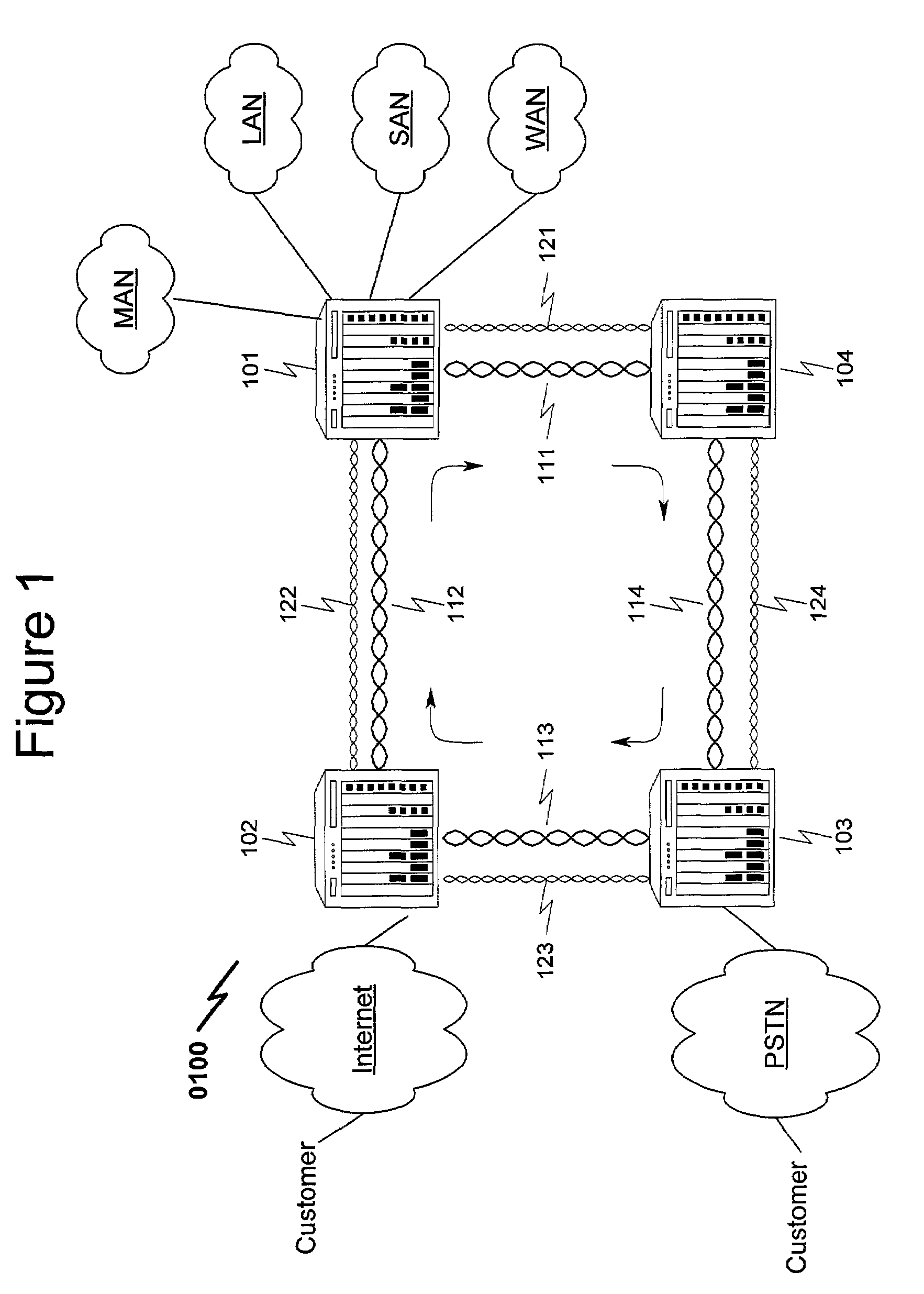
Three kinds of equipment faults may occur in the network in this system:1. a node fails completely, perhaps severing the ring;2. a link fails completely, severing the ring; or3. a node is functioning incorrectly without severing the ring.

Method used


Image

  • Dynamic communication channel allocation method and system
  • Dynamic communication channel allocation method and system
  • Dynamic communication channel allocation method and system

Examples


Embodiment Construction

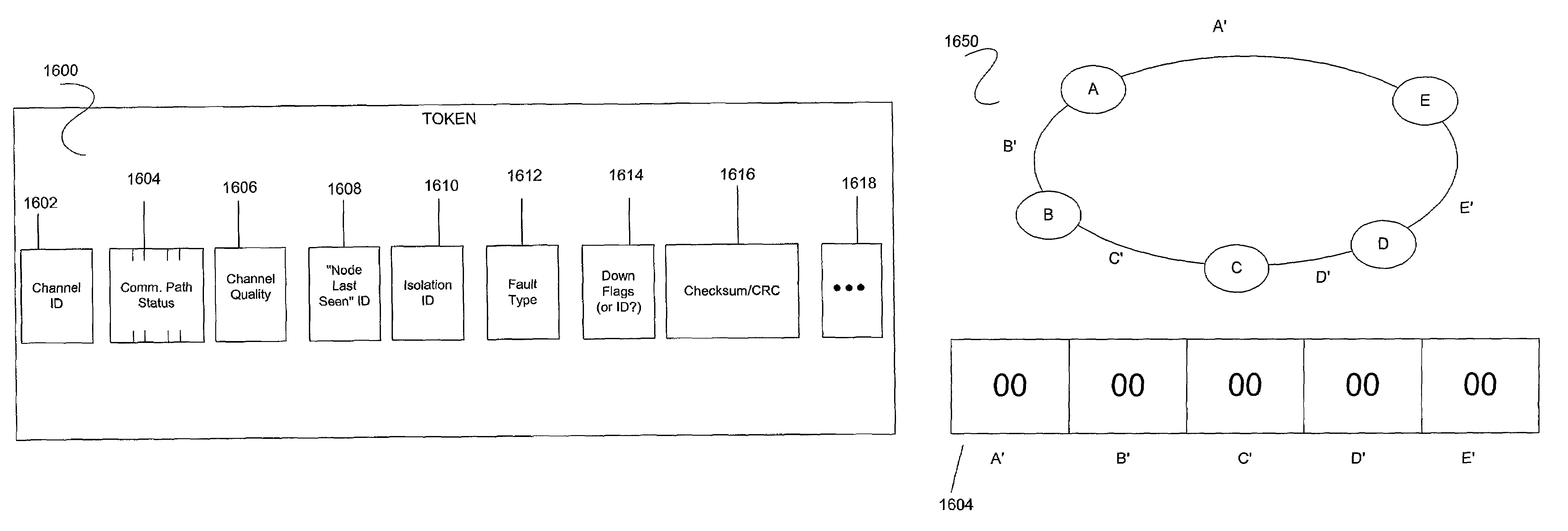
[0103]The teachings of the present invention build on ideas and architecture, described in ““A Token Based Protocol For Integrated Packet and Circuit Switching in WDM Rings,”” by A. Fumagalli, J. Cai, and I. Chlamtac, published in Proceedings of Globecom (Conference on Global Communications), 1998. However, in contrast to their simpler one-bit per link token, the present invention expands the functionality of the token. Referring to FIG. 15, each link can carry a plurality of communication channels (C0 to Cn). One channel, C0, is reserved as a control channel while the remaining channels C1 to Cn are used to carry data payloads. Each data payload channel has a token that is carried on the control channel and identified to the specific data channel. For a fiber optic network, each channel might correlate to a specific wavelength in a WDM medium.

[0104]1. Token Innovation

[0105]FIG. 16a illustrates one embodiment (1600) of the present token scheme. The token (1600) can comprise a number...


PUM


Abstract

A bandwidth brokering system and method incorporating methodology for supporting self-healing communication rings is disclosed. The present invention utilizes state-based tokens that are transmitted on a separate communication channel between network nodes to monitor and correct communication failures occurring at a link, interface, and network node level. The invention as taught permits generic brokering of all available network bandwidth in a granular method without the need for fixed designations of “protection” or “working” communication paths. As such, the present invention permits integration of “protection” and “working” communication data paths to permit full utilization of available system bandwidth with graceful recovery in the event of system or link malfunctions. While the present invention is optimally adapted to use in optical communications systems and specifically those incorporating wavelength division multiplexing (WDM), dense wavelength division multiplexing (DWDM), and ultra-dense wavelength division multiplexing, the teachings presented are equally well adapted to situations where other communications mediums are utilized in a multi-carrier, wireless, or spread-spectrum environment, among others.

Description

RELATED APPLICATION[0001]The present invention is related to provisional application Ser. No. 60 / 282,318 filed on Apr. 6, 2001 and claim is made to this earlier filing date.BACKGROUND OF THE INVENTION[0002]1. Field of the Invention[0003]The present invention relates to a fully distributed method of dynamically allocating bandwidth, as represented by communication channels, between various nodes in a network. Specifically, the method involves the use of a token of information for each available network communication channel (C1 through Cn) wherein the token(s) are transmitted over a control communication channel (C0). Each node looks only at the control channel tokens to determine if a data payload is destined for and simultaneously arriving at that node on one of the communication channels. The method and system are particularly useful in allocating bandwidth for “bursty” data traffic.[0004]2. Abbreviations[0005]A variety of abbreviations will be provided to aid the reader. This inf...

Claims


Application Information

Patent Timeline
Patent Type & Authority Patents(United States)
IPC IPC(8): H04L12/427H04J3/08H04J3/16H04J14/02H04L12/437
CPCH04J3/085H04J3/1682H04J14/0227H04J14/0283H04J14/0291H04L12/437H04J14/0241
Inventor MONTGOMERY, JR., CHARLES D.
Owner MONTGOMERY JR CHARLES D
Learn More