Motor driving device and electric power steering apparatus
a technology of electric power steering and motors, which is applied in the direction of dynamo-electric converter control, instruments, code conversion, etc., can solve the problems of noise, difficult to heighten a voltage for high output and high efficiency, and small inductance value of winding wires of motors used for electric power steering apparatuses
- Summary
- Abstract
- Description
- Claims
- Application Information
AI Technical Summary
Problems solved by technology
Method used
Image
Examples
embodiment 1
[Embodiment 1]
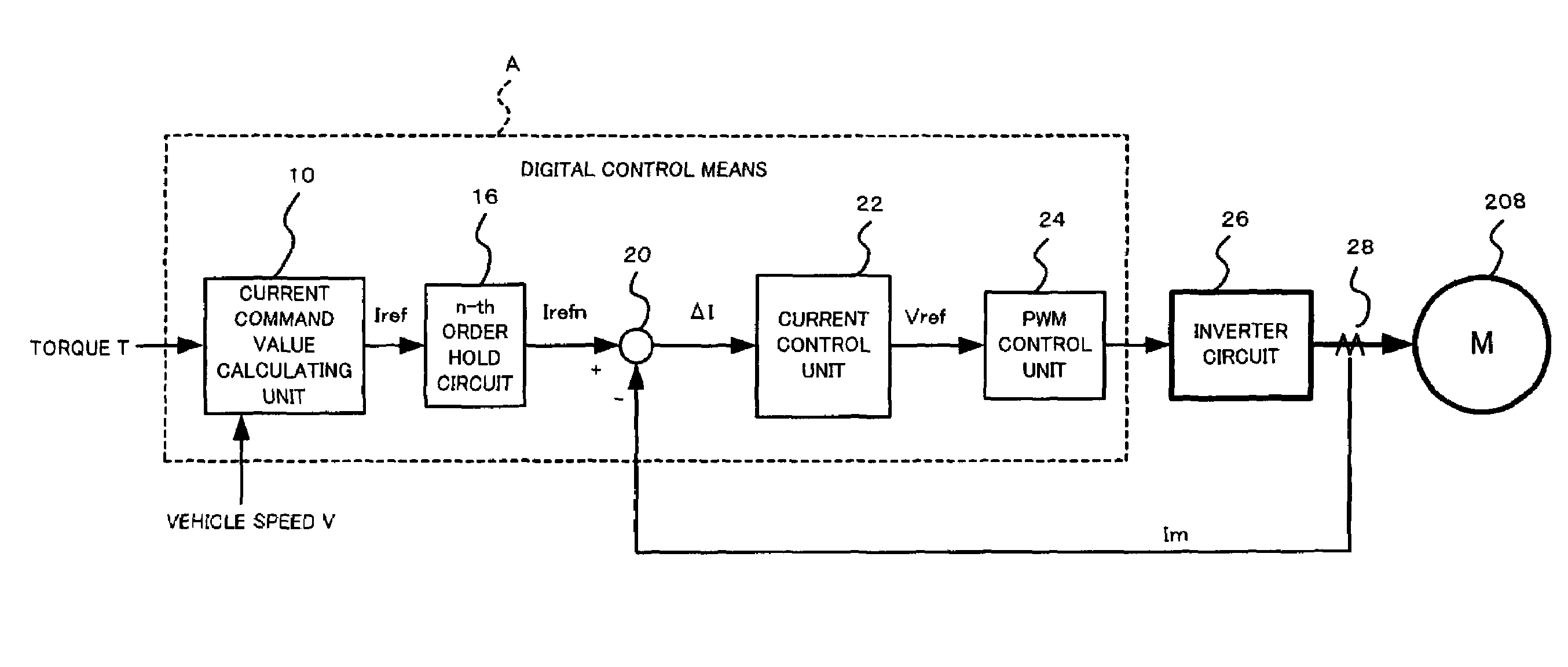
[0043]FIG. 6 is a control block diagram illustrating embodiment 1 of the motor driving device according to the present invention. As shown in FIG. 6, an n-th-order hold circuit 16 as the n-th-order hold means is provided at later part of a current command value calculating unit 10 as the current command value calculating means.
[0044]In FIG. 6, first, the current command value calculating unit 10 as the current command value calculating means calculates a current command value Iref by using a vehicle speed V and a torque T as its inputs, and the current command value Iref is output from the current command value calculating unit 10 to the n-th-order hold circuit 16 as the n-th-order hold means. Next, the current command value Iref is n-th-order-held by the n-th-order hold circuit 16 and is output as a current command value Irefn from the n-th-order hold circuit 16 so as to be inputted into a subtracting unit 20.
[0045]On the other hand, a motor current Im detected by a c...
embodiment 2
[Embodiment 2]
[0102]Next, embodiment 2 in which three or more control means having different sampling periods are present is explained below with reference to FIG. 14. A difference between construction of embodiment 2 in FIG. 14 and construction of embodiment 1 in FIG. 6 is that besides the n-th-order hold circuit 16 provided between the current command value calculating unit 10 and the current control unit 22, an n-th-order hold circuit 18 as the n-th-order hold means is further provided between the current control unit 22 and the PWM control unit 24.
[0103]Here, for example, the sampling periods of the current command value calculating unit 10, the current control unit 22 and the PWM control unit 24 are 2 ms, 1 ms and 0.5 ms, respectively. In embodiment 1, the quantization error due to the difference in the sampling periods between the current command value calculating unit 10 and the current control unit 22 is eliminated by the n-th-order hold circuit 16. In embodiment 2, however,...
PUM
 Abstract
Description
Claims
Application Information
 - Generate Ideas
- Intellectual Property
- Life Sciences
- Materials
- Tech Scout
- Unparalleled Data Quality
- Higher Quality Content
- 60% Fewer Hallucinations
Browse by: Latest US Patents, China's latest patents, Technical Efficacy Thesaurus, Application Domain, Technology Topic, Popular Technical Reports.
© 2025 PatSnap. All rights reserved.Legal|Privacy policy|Modern Slavery Act Transparency Statement|Sitemap|About US| Contact US: help@patsnap.com


