
Method for simulating local prestack depth migrated seismic images

a seismic image and local prestack technology, applied in seismology, geological measurements, instruments, etc., can solve the problems of limited ability to distinguish small-scale structures, not all reflectors are properly illuminated, and the elastic wave generated by artificial sources is not stabl

Active Publication Date: 2008-05-20
NORSAR
View PDF9 Cites 80 Cited by
  • Summary
  • Abstract
  • Description
  • Claims
  • Application Information

AI Technical Summary

Benefits of technology

"The patent text describes a new method for simulating seismic data to improve the process of interpreting and mapping the subterranean structures of the earth. This method does not require the generation of synthetic data and can be used in real-life applications. It uses a background model to efficiently simulate depth migrated sections, which are important for oil exploration. The method can be used in various fields such as seismic surveying, interpretation, and AVO / AVA analysis. It is not restricted to seismic applications and can also be used in other areas such as Ground Penetrating Radar and medical imaging. The method is efficient and fast, and can help improve the accuracy of seismic data interpretation."

Problems solved by technology

Elastic waves generated by artificial sources, such as those used in oil exploration, and propagating through the earth down to several kilometers, have limited capacities to distinguish small-scale structures.
In addition, not all the reflectors are properly illuminated depending on the geometry of the survey and the way waves propagate in complicated earth structures.
So, in addition to the cost of generating those data, the processing cost will be the same as for real data Moreover, no modeling technique is perfect, and their inherent limits might prevent their use.
Ray tracing methods can calculate synthetic data rather quickly, for chosen reflectors, but might also suffer from the high-frequency limit inherent in the method.
Missing reflected events and possibly overestimated amplitudes at caustics might generate disturbing noise on the migrated sections.
But the cost of this modeling is extremely high (executing time and memory requirements), especially in 3D models.
But a stack of horizontal, homogeneous layers is usually a poor model of the earth and will not properly describe the actual 2D / 3D heterogeneity of the structures and its implications on wave propagation.

Method used


Image

  • Method for simulating local prestack depth migrated seismic images
  • Method for simulating local prestack depth migrated seismic images
  • Method for simulating local prestack depth migrated seismic images

Examples


Embodiment Construction

[0042]To properly and completely introduce the present invention, a review of the local imaging technique, as introduced in ([9], [10], [11], [12], [13]) and not yet well known in the seismic community, is necessary to acquire a good understanding of the data-based imaging approach, which will then help understanding the present invention.

[0043]PreStack Depth Migration (PSDM) should be the ultimate stage of a seismic processing sequence, although post- / pre-stack time migration might be sufficient for the interpreters. The goal is to obtain good-quality depth images of the reflecting / diffracting structures, as perceived by the elastic waves generated in a seismic acquisition. A powerful approach in both seismic modeling and processing is to consider the reflecting structures in the earth as sets of point scatterers radiating back the incident energy (see the concept of exploding reflector for instance, [1]). The scattered energy is recorded and PSDM is the tool used to focus this ene...


PUM


Abstract

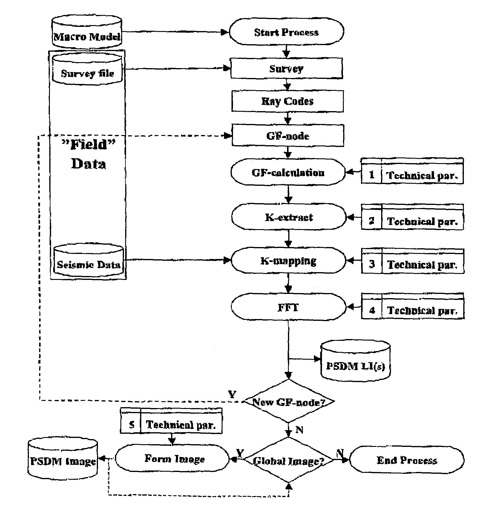
A method, article of manufacture, and data set for simulating seismic prestack depth migrated images on the basis of a model of a selected GF-node, without the use of real or synthetic recorded data, provides a very efficient and flexible way to calculate a simulated depth migrated image as a function of parameters such as survey, overburden model, pulse, elastic wavefield, and local reflectivity structure. Important information needed for the method is the scattering wavenumber, calculated for example, by ray methods and other equivalent methods. Complex model geometry can be done in 2-D and 3-D.

Description

BACKGROUND OF THE INVENTION[0001]The ultimate goal of seismics is to find the elastic properties of the subsurface. Seismic energy in the form of compressional or shear waves is transmitted into the ground, and the reflections (echoes) from structures in the subsurface are recorded by sensors (hydrophones or geophones) most commonly located at, or near, the surface of the earth.[0002]The wavefield recorded by the sensors is then processed in computers. The resulting “sound images” of the subsurface are interpreted by geophysicists and geologists to make maps of the reflecting structures. These structures are interpreted as interfaces (reflectors), which are reflecting because separating layers with different elastic properties. Such elastic property changes might indicate rock variations and other geological / petrophysical features, which in turn could indicate possible oil / gas traps.[0003]The “sound images” obtained after data processing are also called migrated sections or migrated...

Claims


Application Information

Patent Timeline
Patent Type & Authority Patents(United States)
IPC IPC(8): G06F17/50G01V1/00G03H3/00G01V1/28
CPCG01V1/282G01V1/286G01V2210/614G01V2210/512
Inventor LECOMTE, ISABELLE
Owner NORSAR
Learn More