
Braille cell cap

a cell cap and braille technology, applied in the field of braille readers, can solve the problems of increasing the manufacturing cost of each bimorph reed, rough reading surface, gap between the braille cell and its surrounding enclosure, etc., and achieves the effect of reducing labor requirements, improving utility and reliability, and reducing manufacturing costs

Active Publication Date: 2008-05-06
FREEDOM SCI
View PDF19 Cites 27 Cited by
  • Summary
  • Abstract
  • Description
  • Claims
  • Application Information

AI Technical Summary

Benefits of technology

[0009]A special metallic plating is applied to the outer piezo-ceramic contacts to enable soldering of the leads to a printed circuit board (PCB). The need for such special metallic plating increases the manufacturing costs associated with each bimorph reed.
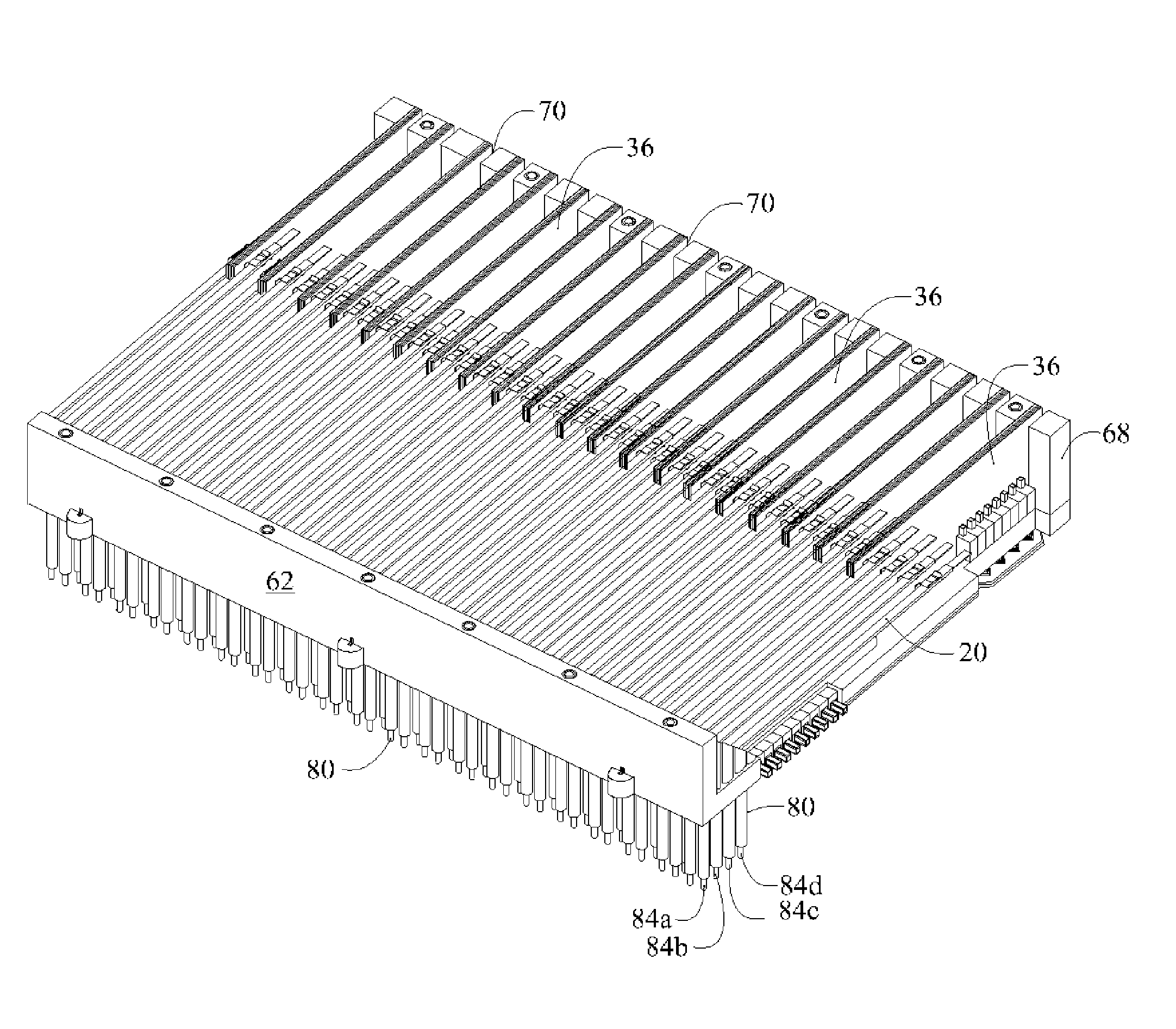
[0034]Each PCB has a protuberance formed in its lowermost, trailing end. A corresponding plurality of slots is formed in the bottom edge of the flat wall of the frame to respectively receive the protuberances to thereby enhance the mounting of the PCBs within the frame.

Problems solved by technology

The need for such special metallic plating increases the manufacturing costs associated with each bimorph reed.
This results in a reading surface that is rough because it includes grooves, gaps and steps between the individual caps.
The individual tolerances of each Braille cell results in a gap between the Braille cells and their surrounding enclosure.
Moreover, the assembly of each Braille cell cap drives up the cost of manufacturing.
The use of individual cell caps for each Braille cell increases the manufacturing cost as aforesaid as well as the cost of materials.
This unevenness between each cell is a limitation of all Braille displays heretofore known.
Additionally, maintenance and replacement of the individual tactile pins is often necessary.
The time required to manufacture a plurality of caps, each of which must be within certain tolerance limits, and to individually cap each Braille cell drives up the cost of manufacturing.
This approach is unsatisfactory because it further accentuates the unevenness of the display and provides additional area for contaminates.
The mounting of bimorph reeds has also been a source of problems.

Method used


Image

  • Braille cell cap
  • Braille cell cap
  • Braille cell cap

Examples


Embodiment Construction

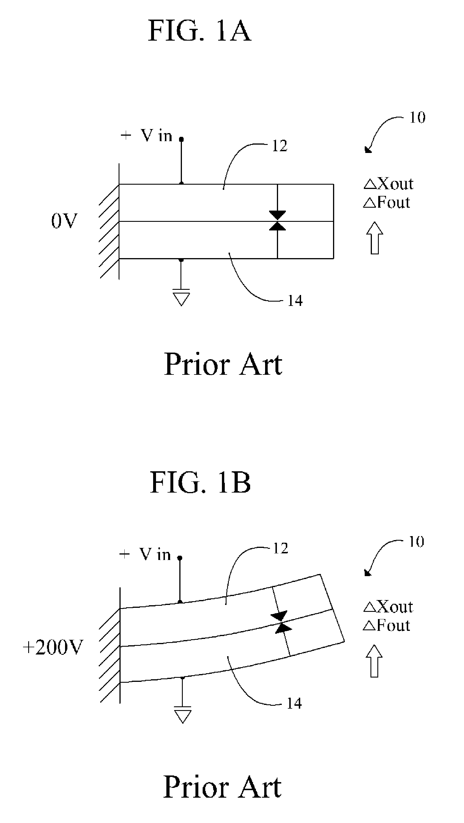
[0072]Referring briefly to FIGS. 1A and 1B, it will there be seen that prior art series x-polled bimorph 10 is excited on only one side of the element. In FIG. 1A, the reference numeral 10 denotes the bimorph when no voltage is applied thereto. A bimorph is made of two strips of conductors that expand longitudinally at different expansion rates when voltage is applied thereto. Accordingly, conductors 12 and 14 share a common length when no voltage is applied thereto as depicted in FIG. 1A.

[0073]In FIG. 1B, 200 volts is applied to prior art bimorph 10. In this particular example, the expansion rate of conductor 14 exceeds that of conductor 12 so that the length of conductor 14 exceeds that of conductor 12 when voltage is applied to conductor 12. Bimorph 10 therefore becomes curved. The amount of curvature increases in direct relation to an increase in applied voltage. No voltage is applied to the central electrode in a series-polled bimorph.

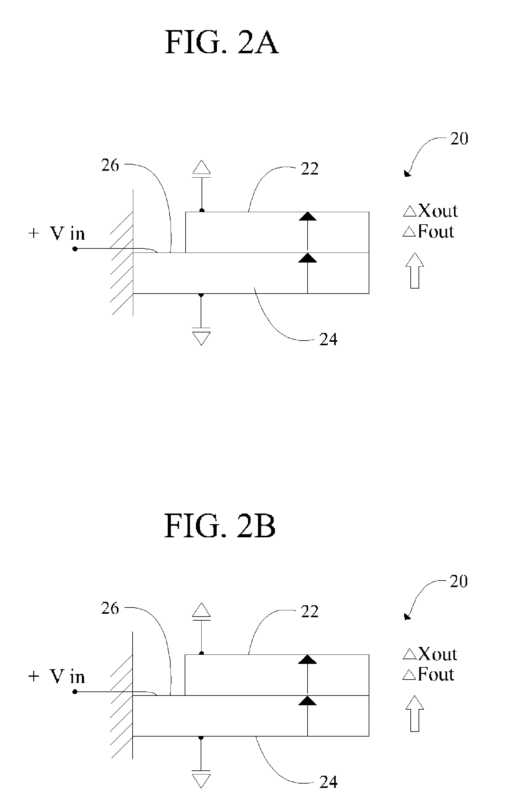
[0074]Turning now to FIGS. 2A and 2B, there...


PUM


Abstract

An electromechanical Braille cell assembly includes a plurality of parallel bimorph reeds. A first plurality of bimorph reeds is mounted to a first side of a printed circuit board by a first plurality of clips and a second plurality of bimorph reeds is mounted to a second side of the printed circuit board by a second plurality of clips. A frame has a top wall, a bottom wall, a first side wall in the form of an angle wall and a second side wall in the form of a flat wall. Pinholes are formed in the angle wall to accommodate Braille pins and the flat wall is slotted to accommodate a plurality of printed circuit boards. A monolithic cap covers all of the Braille pins. Pinholes formed in the cap receive the respective tips of the Braille cells when actuated bimorph reeds cause displacement of the Braille pins.

Description

CROSS REFERENCE TO RELATED DISCLOSURE[0001]This application claims priority to Provisional Patent Application No. 60 / 481,979, filed Jan. 30, 2004 by the same inventors.BACKGROUND OF THE INVENTION[0002]1. Field of the Invention[0003]This invention relates, generally, to Braille readers. More particularly, it relates to a Braille reader that captures information displayed on a computer screen and transforms the information into Braille.[0004]2. Description of the Prior Art[0005]Electronic devices that capture written information on a computer screen and transform the information into Braille are known. The known devices incorporate Braille cells that may include a plurality of hollow housings of parallelepiped construction, each of which houses either six (6) or eight (8) Braille pins. In the alternative, the housings may be solid and provided with bores for receiving the Braille pins. The pins are arranged in two (2) columns of three (3) or four (4) pins each.[0006]When in repose, ea...

Claims


Application Information

Patent Timeline
IPC IPC(8): G09B21/00
CPCG09B21/004
Inventor MURPHY, PATRICKCONARD, TODDTUNKIS, WALDEMAR H.GOLDENBERG, MICHAELRODRIGUEZ, CARLOS M.
Owner FREEDOM SCI
Learn More