
Method of making an acoustically coupled transformer

a transformer and acoustic field technology, applied in the direction of generator/motor, piezoelectric/electrostrictive device material selection, piezoelectric/electrostrictive device, etc., can solve the problems of coil-based transformers becoming impractical, not all transformers have all of these properties, etc., to achieve low manufacturing cost, low insertion loss, bandwidth sufficient

Inactive Publication Date: 2008-05-06
AVAGO TECH INT SALES PTE LTD
View PDF257 Cites 70 Cited by
  • Summary
  • Abstract
  • Description
  • Claims
  • Application Information

AI Technical Summary

Benefits of technology

[0014]Embodiments of an acoustically-coupled transformer in accordance with the invention are capable of providing one or more of the following attributes at electrical frequencies in the range from UHF to microwave: impedance transformation, coupling between balanced and unbalanced circuits and electrical isolation. Such embodiments typically have a low insertion loss, a bandwidth sufficient to accommodate the frequency range of cellular telephone RF signals, for example, a size smaller than transformers currently used in cellular telephones and a low manufacturing cost.

Problems solved by technology

However, not all transformers have all of these properties.
For example, an auto-transformer does not provide electrical isolation.
At UHF and microwave frequencies, coil-based transformers become impractical due to such factors as losses in the core, losses in the windings, capacitance between the windings, and a difficulty to make them small enough to prevent wavelength-related problems.
Transformers also exist that are based on micro-machined coupled coils sets and are small enough that wavelength effects are unimportant.
However such transformers have issues with high insertion loss.
All the transformers just described for use at UHF and microwave frequencies have dimensions that make them less desirable for use in modem miniature, high-density applications such as cellular telephones.
Such transformers also tend to be high in cost because they are not capable of being manufactured by a batch process and because they are essentially an off-chip solution.
Moreover, although such transformers typically have a bandwidth that is acceptable for use in cellular telephones, they typically have an insertion loss greater than 1 dB, which is too high.
Opto-couplers are not used at UHF and microwave frequencies due to the junction capacitance of the input LED, non-linearities inherent in the photodetector limited power handling capability and insufficient isolation to give good common mode rejection.

Method used


Image

  • Method of making an acoustically coupled transformer
  • Method of making an acoustically coupled transformer
  • Method of making an acoustically coupled transformer

Examples


Embodiment Construction

[0026]Film bulk acoustic resonators (FBARs) are disclosed by Ruby et al. in U.S. patent No. 5,587,620 entitled Tunable Thin Film Acoustic Resonators and Method of Making Same, now assigned to the assignee of this disclosure and incorporated in this disclosure by reference. Ruby's disclosure also discloses a stacked film bulk acoustic resonator (SBAR) composed of two layers of piezoelectric material interleaved with three planar electrodes. Ruby's SBAR can be regarded as being composed of a stacked pair of FBARs in which one electrode is common to both FBARs, and will be referred to as a common-electrode SBAR. The common electrode renders the common-electrode SBAR incapable of linking balanced to unbalanced circuits and vice versa and of providing electrical isolation between primary and secondary. Moreover, the common electrode SBAR exhibits an extremely narrow pass bandwidth that makes it unsuitable for use in most applications. The narrow pass bandwidth is the result of the common...


PUM

PropertyMeasurementUnit
insertion lossaaaaaaaaaa
thicknessaaaaaaaaaa
frequencyaaaaaaaaaa

Abstract

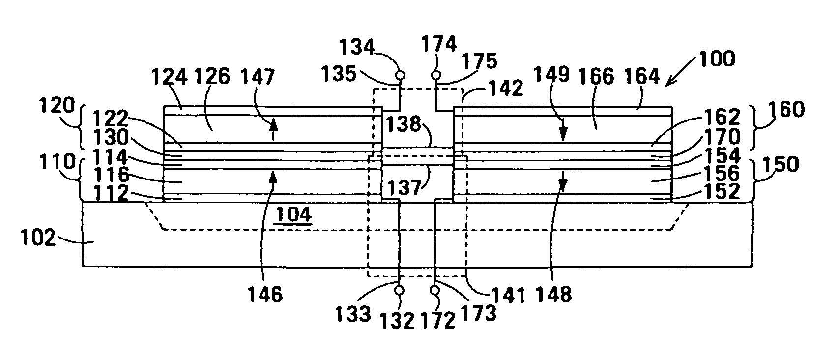
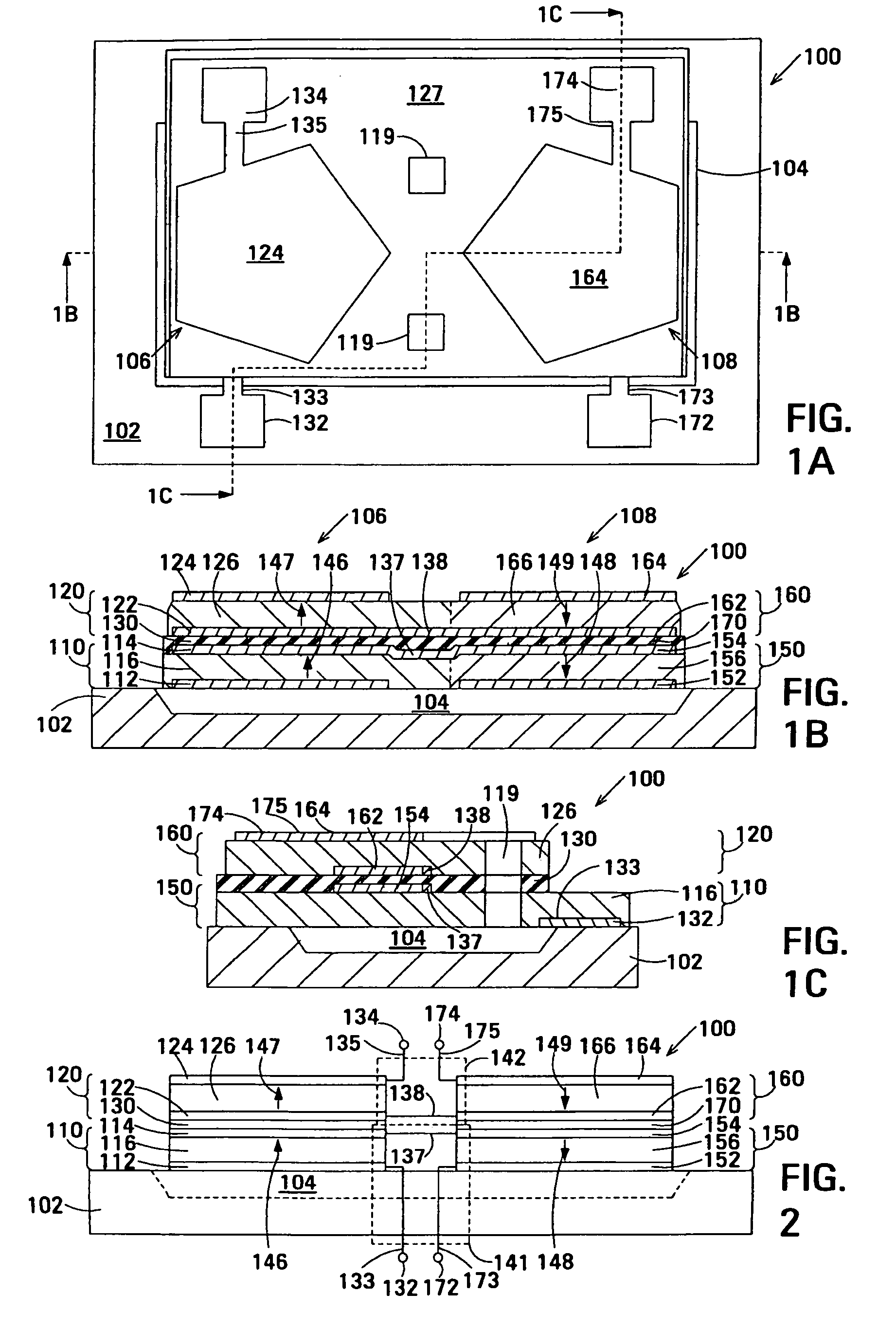
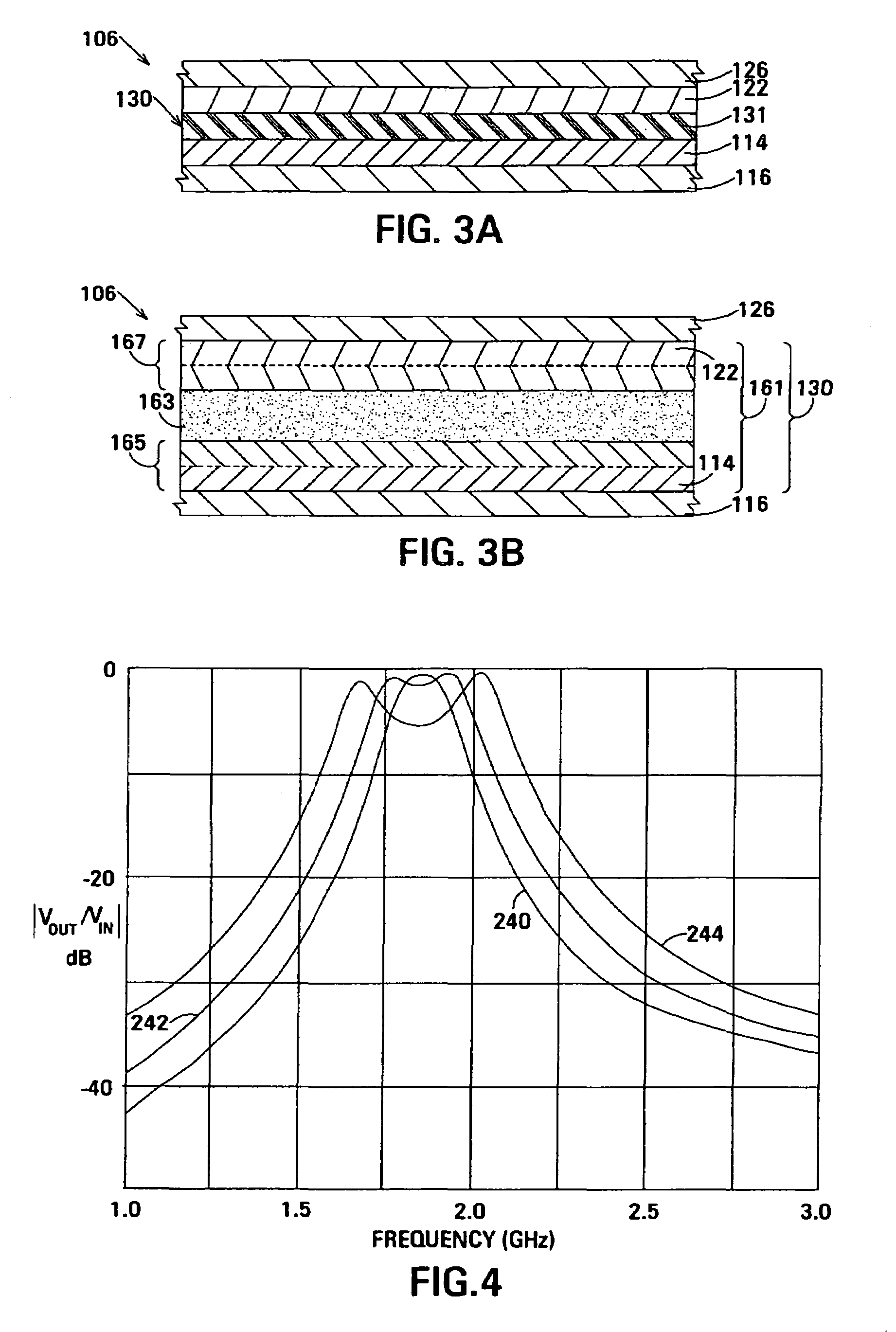
Embodiments of an acoustically-coupled transformer have a first stacked bulk acoustic resonator (SBAR) and a second SBAR. Each of the SBARs has a lower film bulk acoustic resonator (FBAR) and an upper FBAR, and an acoustic decoupler between the FBARs. The upper FBAR is stacked atop the lower FBAR. Each FBAR has opposed planar electrodes and a piezoelectric element between the electrodes. The piezoelectric element is characterized by a c-axis. The c-axes of the piezoelectric elements of the lower FBARs are opposite in direction, and the c-axes of the piezoelectric elements of the upper FBARs are opposite in direction. The transformer additionally has a first electrical circuit connecting the lower FBAR of the first SBAR to the lower FBAR of the second SBAR, and a second electrical circuit connecting the upper FBAR of the first SBAR to the upper FBARs of the second SBAR.

Description

CROSS-REFERENCE TO RELATED APPLICATIONS[0001]This application is a divisional of U.S. patent application Ser. No. 10 / 836,663, filed on Apr. 29, 2004 now U.S. Pat No. 7,091,649, which is a continuation-in-part of U.S. patent application Ser. No. 10 / 699,481, filed Oct. 30, 2003 now U.S. Pat. No. 6,946,928, and is related to U.S. patent application Ser. No.10 / 836,653 of Larson III et al. entitled Film Acoustically-Coupled Transformer with Reverse C-Axis Piezoelectric Material filed on Apr. 29, 2004, now U.S. Pat. No. 6,987,433 B2 and which is incorporated herein by reference in its entirety.BACKGROUND[0002]Transformers are used in many types of electronic device to perform such functions as transforming impedances, linking single-ended circuitry with balanced circuitry or vice versa and providing electrical isolation. However, not all transformers have all of these properties. For example, an auto-transformer does not provide electrical isolation.[0003]Transformers operating at audio a...

Claims


Application Information

Patent Timeline
Patent Type & Authority Patents(United States)
IPC IPC(8): H04R17/00H01L41/00H03H9/02H01L41/09H01L41/08H01L41/18H01L41/22H01L41/257H01L41/319H03H3/02H03H9/13H03H9/17H03H9/60
CPCH03H9/132H03H9/584H03H9/587H03H9/605Y10T29/49155Y10T29/42Y10T29/4902Y10T29/49128
Inventor LARSON, III, JOHN D.OSHMYANSKY, YURY
Owner AVAGO TECH INT SALES PTE LTD
Learn More