Data receiving and transmitting method with coding type determination

Inactive Publication Date: 2008-04-29
HIGHBRIDGE PRINCIPAL STRATEGIES LLC AS COLLATERAL AGENT
View PDF18 Cites 2 Cited by
  • Summary
  • Abstract
  • Description
  • Claims
  • Application Information

AI Technical Summary

Benefits of technology

[0022]An object of the present invention is to provide a data communication system transmitting data to which adaptive modulation at an acknowledged data transfer mode is simultaneously applied by considering a data transfer rate varying in accordance with radio environments as well as guaranteeing security of data transfer.

Problems solved by technology

Yet, the related art has failed to propose a system realizing method considering both data transfer and adaptive modulation at the acknowledged data transfer simultaneously.
In the related art, the radio link connection should be reestablished so as to guarantee the transmission security of single information, thereby bringing about inefficiency of transmission delay.
Nevertheless, the transmission delay of packets still occurs as well as the probability of error occurrence in the transmitted packets increases.

Method used


Image

  • Data receiving and transmitting method with coding type determination
  • Data receiving and transmitting method with coding type determination
  • Data receiving and transmitting method with coding type determination

Examples


first embodiment

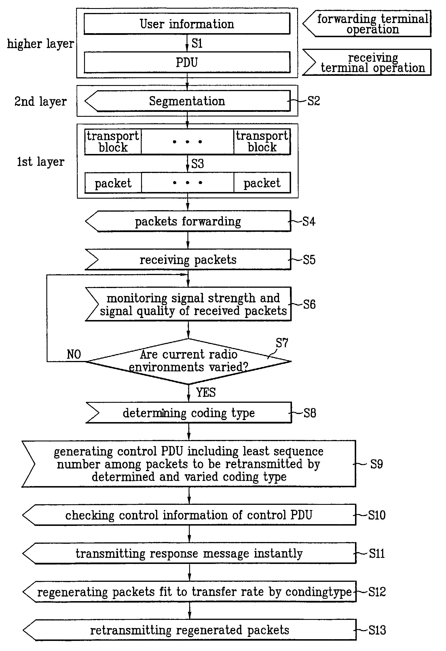
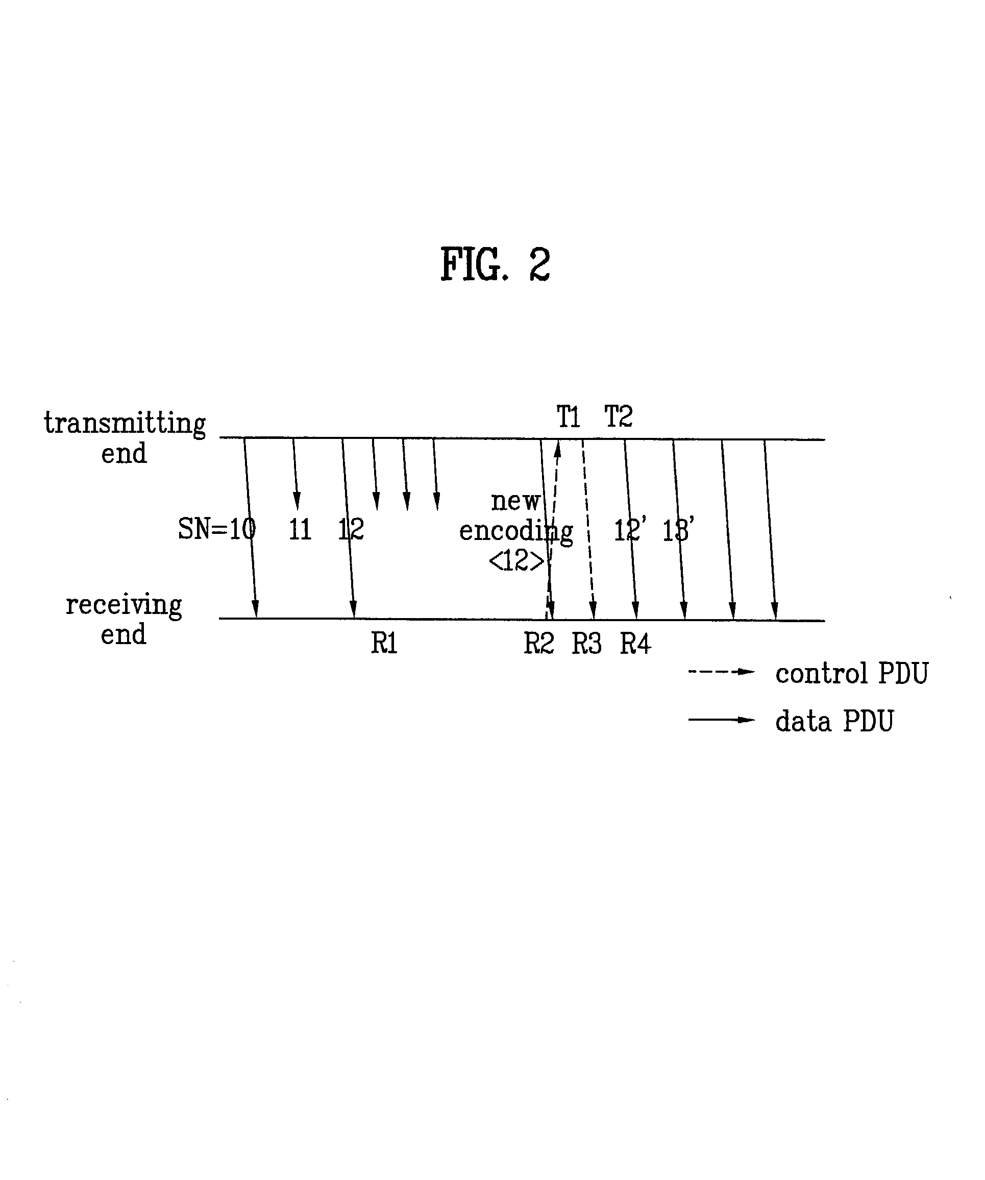
[0046]FIG. 2 illustrates a diagram for a data communication method of an instant switching system according to the present invention.

[0047]Shown in FIG. 2 is a case that packets, to which sequence numbers(hereinafter abbreviated SN), 0 to 15, are given, are forwarded using adaptive modulation.

[0048]Namely, shown is the case that a data transfer rate is changed while a twelfth packet among the packets forwarded from a transmitting end is being transferred. A receiving end determines the data transfer rate of the transmitting end for the variation of the radio environments so as to inform a transfer rate of data that will be transmitted.

[0049]In this case, the receiving end receives a varied coding type and application of the varied coding type so as to form a control PDU including control information to inform the transmitting end of a least sequence number(SN=2 in FIG. 2) among the packets to be retransmitted. The receiving end then transfers the control PDU to the transmitting end....

second embodiment

[0062]FIG. 4 illustrates a diagram for a data communication method of a delay response system according to the present invention.

[0063]Shown in FIG. 4 is the case that packets to which SNs, 0 to N, are given respectively are forwarded using adaptive modulation.

[0064]Namely, shown is the case that a data transfer rate is changed by the variation of radio environments, while eleventh and twelfth packets among the packets forwarded from a transmitting end are being transferred, so as to lose the two packets. In this case, a receiving end determines the data transfer rate of the transmitting end for the variation of the radio environments so as to inform a data transfer rate that will be transmitted.

[0065]The receiving end forms a control PDU including control information for informing the transmitting end of the variation of a coding type, a SN(latest sequence number, LSN) of the lately received packet, and SNs(SN=11, 12 in FIG. 4) of the packets lost during transmission(packets failin...


PUM


Abstract

Disclosed is a data communication system transmitting data using adaptive modulation at an acknowledged data transfer mode simultaneously. The present invention includes a first step of monitoring variation of radio environments by a receiving end receiving packets sequentially, a second step of determining a coding type to be varied in accordance with the variation of the radio environments in the receiving end so as to inform a transmitting end of the determined coding type, and a third step of forwarding sequentially the corresponding packets with a transfer rate in accordance with the determined coding type in the transmitting end.

Description

[0001]This application claims the benefit of the Korean Application No. P2001-41895 filed on Jul. 12, 2001, which is hereby incorporated by reference.BACKGROUND OF THE INVENTION[0002]1. Field of the Invention[0003]The present invention relates to a next generation mobile communication system, and more particularly, to a data communication system transmitting data using adaptive modulation at an acknowledged data transfer mode simultaneously.[0004]2. Discussion of the Related Art[0005]Generally, a protocol for realizing a data communication system is divided into first, second, third, . . . and higher layers.[0006]The first layer is a physical layer, in which encoding / decoding of data, rate matching, modulation / demodulation, spreading / dispreading and the like are defined.[0007]The second layer includes two sub-layers such as a MAC(medium access control) layer and a RLC(radio link control) layer.[0008]The MAC layer provides services such as data transfer, reporting of measurements(suc...

Claims


Application Information

Patent Timeline
IPC IPC(8): H04B7/00H04L29/10H04B7/26H04L1/00H04L1/16H04L1/18H04L12/06H04W28/00H04W28/04H04W28/06H04W28/18H04W72/08
CPCH04L1/1867H04L1/0015H04L1/1671H04L1/0003H04L1/0009H04L1/0025
Inventor AHN, HEE JUN
Owner HIGHBRIDGE PRINCIPAL STRATEGIES LLC AS COLLATERAL AGENT
Why Eureka
Try Eureka