Communication apparatus and method

Inactive Publication Date: 2010-09-16
HITACHI CONSUMER ELECTRONICS CORP
View PDF5 Cites 0 Cited by
  • Summary
  • Abstract
  • Description
  • Claims
  • Application Information

AI Technical Summary

Benefits of technology

[0015]According to the means mentioned above, under the condition that the wide-area network enabling to execute a band assurance session, and the in-site network are connected through the communication apparatus, the communication is possible even if not knowing the address of the communication terminal, i.e., the other party, directly, when a communication terminal on a certain in-site network and other in-site network are trying to communicate through the wide-area network mentioned above.

Problems solved by technology

Thus, the communication cannot be made if a first terminal does not know the connection destination information of the other terminal to be connected with.
Thus, it is so constructed that access cannot be made from the communication network side to the equipments on the home LAN, directly.
In the similar manner, it is also impossible to know which kinds of equipments are on the home LAN, or address information of each of the equipments on the home LAN, etc.
Accordingly, publication of the addresses of the equipments on the home LAN to an external communication network has a problem from a viewpoint of practical use thereof.

Method used


Image

  • Communication apparatus and method
  • Communication apparatus and method
  • Communication apparatus and method

Examples


embodiment 1

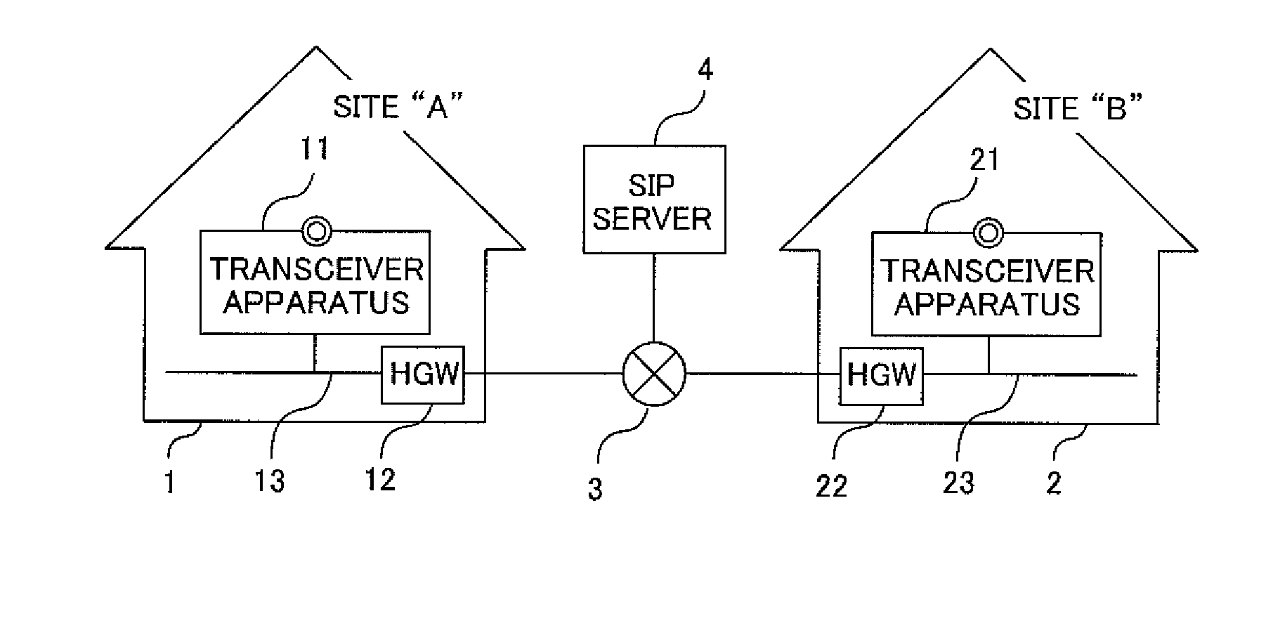
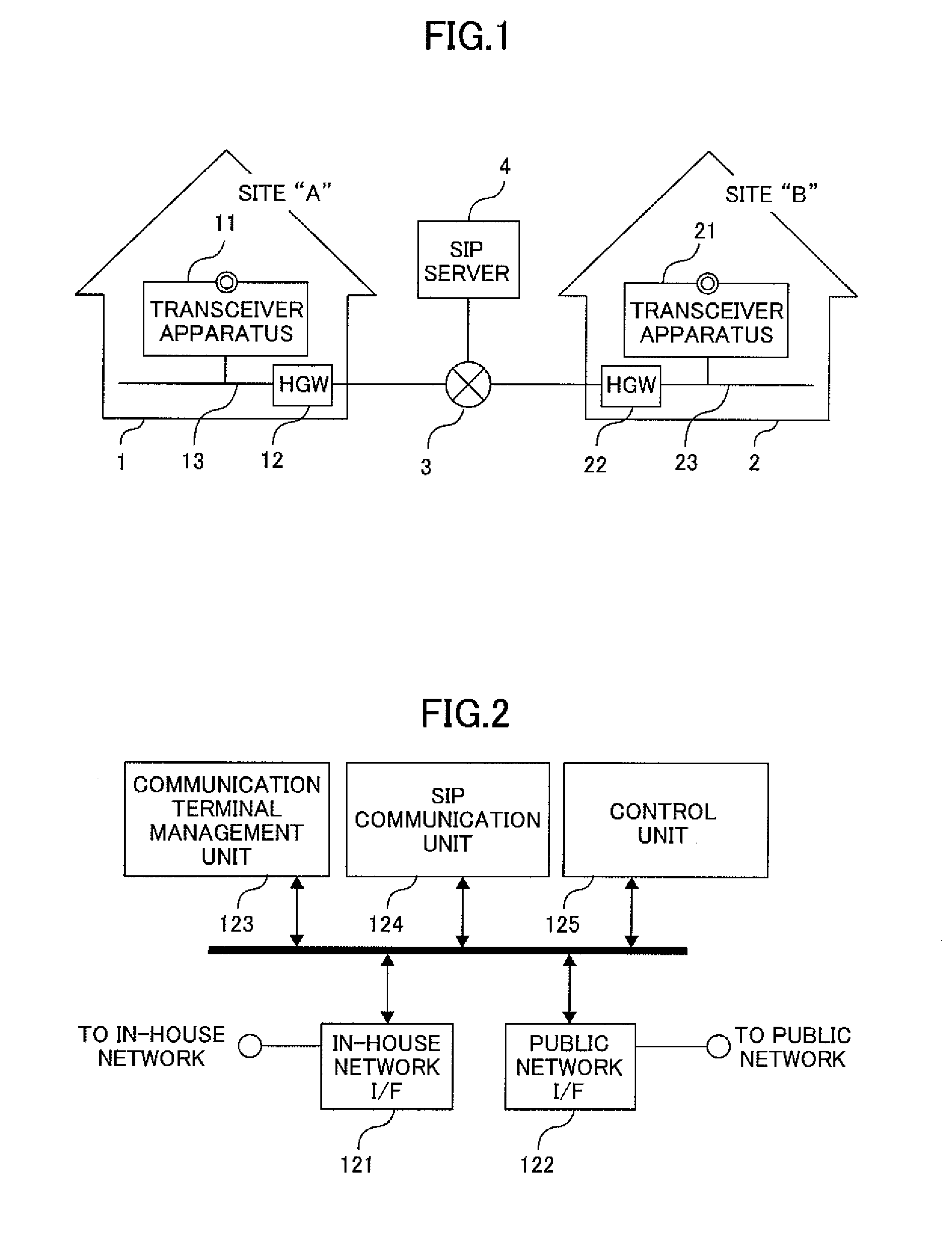
[0027]FIG. 1 shows an example of a media data transmission system for conducting transmission of media data, such as, video and audio, according to an embodiment 1. There are two (2) positions or sites; i.e., a site “A” and a site “B”.

[0028]At the site “A” is provided a transceiver apparatus 11 and a HGW 12, wherein those are connected with each other through an in-house network 13. The HGW 12 is connected with a public network 3. To the transceiver apparatus 11 is assigned an address “A1”, to the HGW 12 an address “A2” on the public network side, and to the in-house network side an address “A3”, respectively.

[0029]In the similar manner, at the site “B” is provided a transceiver apparatus 21 and a HGW 22, wherein those are connected with each other through an in-house network 23. The HGW 22 is connected with the public network 3. To the transceiver apparatus 21 is assigned an address “B1”, to the HGW 22 an address “B2” on the public network side, and to the in-house network side an ...

embodiment 2

[0078]Next, explanation will be made on a second embodiment. The explanation will be omitted, about the portions or elements similar to those in the embodiment 1, and the explanation will be done only about the portions or elements differing from those.

[0079]FIG. 7 shows an example of the starting processes for connecting the communication, according to the present embodiment. The difference from the embodiment 1 lies in that the connection request from the transceiver apparatus 11 to the HGW 12 and the calling request at the application level are integrated or combined in one body.

[0080]Namely, the operations are similar to those in the embodiment 1, in the portions from when the user “UA” conducts the transmission operation until when the “INVITE” message arrives to the HGW 22, so that the HGW 22 repeats the “Trying” message to the SIP server 4. Thereafter, continuing from the above, the calling request is conducted from the HGW 22 to the transceiver apparatus 21.

[0081]The transce...


PUM


Abstract

A communication apparatus, being connected with a wide-area network enabling to execute a band assurance session and an in-site network, for relaying communication between the wide-area network and the in-site network, comprises a communication terminal management means for registering and managing the communication terminal, upon receipt of a first registration request from the communication terminal, which is connected with the in-site network, wherein a second communication start request to said communication terminal, which is registered in the communication management means, upon receipt of a first communication start request from the wide-area network.

Description

INCORPORATION BY REFERENCE[0001]This application relates to and claims priority from Japanese Patent Application No. 2009-060421 filed on Mar. 13, 2009, the entire disclosure of which is incorporated herein by reference.BACKGROUND OF THE INVENTION[0002]The present invention relates to a communication apparatus, a communication terminal, and a communicating method for the same.[0003]Systems are put into practical use, for transmitting media data, such as, audio and video, etc., for example, between parties separated at a long distance, in a real-time manner. Among those, accompanying with wide spreading of the Internet, Vo IP (Voice over IP) and / or a television telephone conference system are put into the practical use, for achieving a telephone function with conducting audio communication on IP (Internet Protocol) network.[0004]When conducting the transmission of media data between two (2) sites, or sites that are connected with through the IP network, as one of the processes for st...

Claims


Application Information

Patent Timeline
IPC IPC(8): H04L12/56H04L47/724H04M3/00H04M11/00
CPCH04L29/12594H04L61/3085H04L65/1006H04L65/1036H04M7/006H04L61/30H04L2101/385H04L65/1104
Inventor MIZOSOE, HIROKIIWABUCHI, KAZUNORI
Owner HITACHI CONSUMER ELECTRONICS CORP
Why Eureka
Try Eureka