
Method and system for mounting photovoltaic material

a photovoltaic material and flexible technology, applied in the field of system and method for mounting flexible photovoltaic material, can solve the problems of labor intensive installation, limited use of adhesive materials, labor intensive steps, etc., and achieve the effect of limiting or eliminating the use of adhesives

Inactive Publication Date: 2008-04-29
UNITED SOLAR OVONIC
View PDF4 Cites 89 Cited by
  • Summary
  • Abstract
  • Description
  • Claims
  • Application Information

AI Technical Summary

Benefits of technology

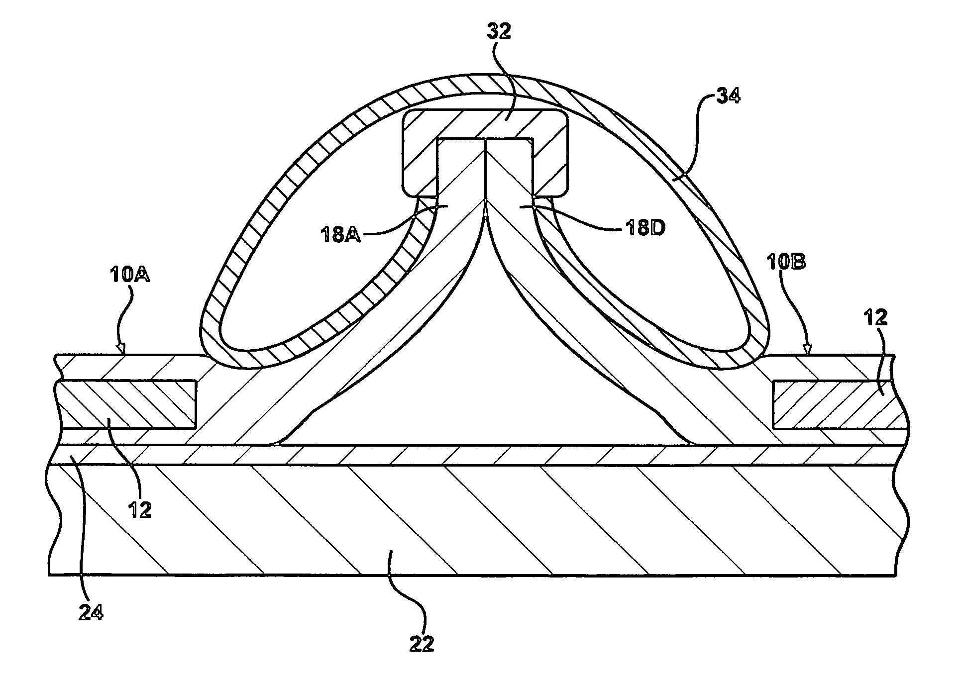
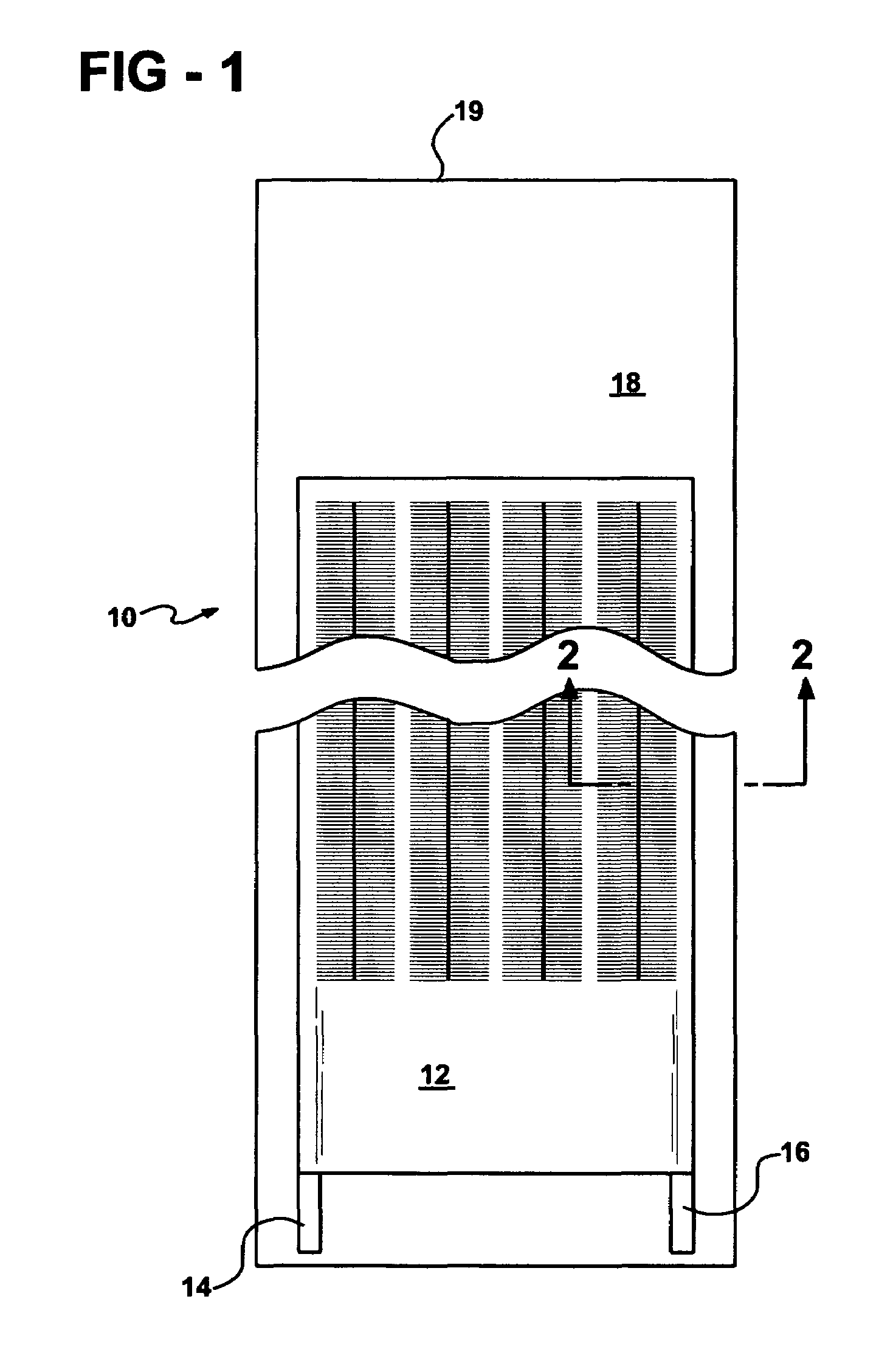
[0011]The present invention discloses a system for securing webs of flexible photovoltaic material to a surface, such as a roof deck. A first flexible web of photovoltaic material and a second web of photovoltaic material are set onto the surface in a longitudinally aligned relationship with one another, wherein a first edge of the first web abuts a first edge of the second web to form a longitudinal engagement point. At least one clamping strip is clamped onto the longitudinal engagement point and at least one batten cap clamped onto the clamping strip(s). Each of said webs have a generally central photovoltaic area encapsulated within a polymeric material and the polymeric material may have both side and end extending edges beyond the photovoltaic area and a pair of contact terminals extending from a selected end of the flexible web and establishing electrical communication with the photovoltaic area. The photovoltaic web may maintain a uniform thickness through the entire area of the web or, preferably, may maintain a uniform thickness throughout cross sections having the photovoltaic area, then taper to a thinner thickness at the edges and sides.
[0013]An embodiment of current application discloses a ridge roller for installing strips of photovoltaic material. The ridge roller rotatably secures a spool of photovoltaic material to facilitate the drawing and sectioning of discreet lengths of photovoltaic material for installation in the manner described above. In one embodiment, the ridge roller comprises a first set of legs adapted to run along a first rail and a second set of legs adapted to run along a second rail. Preferably, the second rail is approximately parallel to said first rail to maintain a smooth transfer as the ridge roller is moved along the ridge and the strips are drawn and sectioned. A cradle is adapted to rotatably support the spool. In another embodiment, the ridge roller comprises a box structure having a first sliding panel and a second sliding panel. The sliding panels are adjusted to allow the ridge roller to run along the ridge without tacks. However, tracks may be added to secure the position of the ridge roller. Wheels are attached to the sliding panels to assist in movement along the ridge. Preferably, at least one first locking means is adapted to lock the first sliding panel into a desired position and at least one second locking means adapted to lock said second sliding panel into a desired position.
[0015]An embodiment of the present invention provides a system for securing flexible photovoltaic roofing material to a roof deck that limits or eliminates the use of adhesives.
[0017]An embodiment of the present invention provides an improved system and method for securing a series of proximately set webs of photovoltaic material onto a surface, such as a roof deck.

Problems solved by technology

However, each cell strip must be interconnected to the next and various interconnections do not incorporate batten caps.
However, the mounting system is very complex and requires labor intensive installation.
Consequently, there exists a need in the art for a method and system for mounting photovoltaic material that securely fastens individual photovoltaic strips or panels to a surface, such as a roof deck, while limiting the use of adhesive materials and labor intensive steps.

Method used


Image

  • Method and system for mounting photovoltaic material
  • Method and system for mounting photovoltaic material
  • Method and system for mounting photovoltaic material

Examples


Embodiment Construction

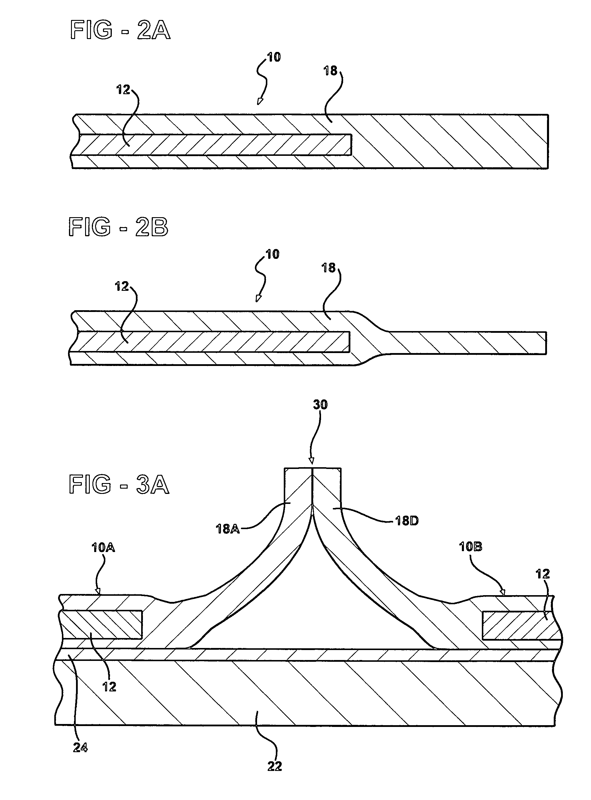
[0044]The present invention discloses a system and method for securing flexible panels, such as a photovoltaic roofing material, to a surface, such as a roof. Referring to FIG. 3A, a cross-sectional view is illustrated of a roof deck 22 showing a first stage in the mounting of two strips 10A and 10B of photovoltaic roofing material onto the roof deck 22. As is shown in this embodiment, a sheet of membrane material 24 may be disposed atop a roof deck 22, the strips of photovoltaic material 10A and 10B being disposed onto.

[0045]The membrane material 24 may be selected from materials including but not limited to tarpaper, polymeric material and natural rubber. Referring now to FIG. 1, a schematic depiction is illustrated at of a web of photovoltaic material 10 that may be used with the present invention. The invention disclosed herein is particularly useful in securing large areas of photovoltaic webs. The present invention discloses a system and method for mounting photovoltaic roofin...


PUM

PropertyMeasurementUnit
flexibleaaaaaaaaaa
electrical communicationaaaaaaaaaa
electrical connectionaaaaaaaaaa

Abstract

The present invention discloses a system and method for mounting a flexible material, such as a web of photovoltaic material, onto a surface, such as a roof. The system and method comprises providing a first and a second elongated web of flexible material and disposing the first and second webs on the surface in a longitudinally aligned relationship with one another, wherein a first edge of said first web abuts a first edge of said second web to form a longitudinal engagement point to produce a substantially triangular shape. At least one clamping strip is secured onto the longitudinal engagement point, wherein the clamping strip(s) is adapted to secure the longitudinal engagement point in a stable position for the length of the web. At least one batten cap is clamped onto the clamping strip(s), wherein the batten cap(s) is adapted to secure the clamping strips. Additionally, securing means, such as screws, nails or adhesives, may be incorporated to attach the sides of the substantially triangular shape to the surface.

Description

RELATED APPLICATION DATA[0001]The present application is filed under 35 USC § 1.53(b) as a Continuation-in-Part of U.S. patent application Ser. No. 10 / 095,391, filed on Mar. 12, 2002 now U.S. Pat. No. 6,730,841, which is hereby incorporated herein by reference.FIELD OF THE INVENTION[0002]The present invention discloses a system and method for securing flexible photovoltaic material onto a surface. More specifically, the invention relates to roof-mounted photovoltaic generating structures and methods for mounting flexible, photovoltaic roofing material onto a roof or deck structure which limits the use of adhesives to secure the material.BACKGROUND OF THE INVENTION[0003]Photovoltaic devices provide silent, nonpolluting, reliable sources of electrical energy. Rooftops and other portions of building structures provide ideal support surfaces for photovoltaic devices, and a large body of art has been developed relating to methods and apparatus for mounting photovoltaic structures onto bu...

Claims


Application Information

Patent Timeline
Patent Type & Authority Patents(United States)
IPC IPC(8): H01L31/048H01L31/042
CPCH01L31/048Y02B10/12Y10T156/1795Y10S136/291H02S20/25Y02E10/50Y02B10/10
Inventor HECKEROTH, STEVE
Owner UNITED SOLAR OVONIC
Learn More