Scroll fluid machine having an adjustment member with a deformable element

a fluid machine and adjustment member technology, applied in the direction of machines/engines, rotary/oscillating piston pump components, liquid fuel engines, etc., can solve the problems of a significant cost increase, and a large amount of power consumption in the power conditioning circuit, so as to reduce the space between the end plate (23) and the wrap (24) and increase the capacity. , the effect of increasing the capacity

Inactive Publication Date: 2008-04-29
DAIKIN IND LTD
View PDF13 Cites 8 Cited by
  • Summary
  • Abstract
  • Description
  • Claims
  • Application Information

AI Technical Summary

Benefits of technology

[0032]According to the present invention, the deformable element (40) is provided at the tip of the wrap (24) to adjust the amount of the space between the wrap (24) and the end plate (23). Therefore, capacity control is easily achieved. Especially, multistage capacity control is achieved because the amount of the space can be varied within a wide range.
[0033]Further, as the capacity control is achieved by merely changing the shape of the deformable element (40), the power required is small. Thus, an improvement in efficiency is expected.
[0034]According to the fourth aspect of the present invention, two or more deformable elements (40) are provided. Therefore, the capacity control is carried out with accuracy.
[0035]According to the fifth aspect of the present invention, the deformable element (40) adjusts the amount of the space to vary the capacity. Therefore, the capacity is controlled with reliability.
[0036]According to the sixth aspect of the present invention, the deformable element (40) at the beginning of the spiral of the wrap (24) increases the amount of the space to adjust an angle of rotation at which fluid discharge begins. Therefore, the compression ratio is controlled.
[0037]According to the seventh aspect of the present invention, the wrap (24) is configured such that the capacity of the working chamber (2a) becomes substantially zero after the discharge is terminated. For example, if the capacity of the closed working chamber is reduced, the compression ratio is reduced. However, if a discharge pressure which is generally high is raised to a further degree, the compression ratio is prevented from reduction.

Problems solved by technology

However, the provision of the power conditioning circuit brings about a problem of a significant cost increase.
Further, the power conditioning circuit consumes a large amount of power and the efficiency decreases due to power loss by the inverter.

Method used


Image

  • Scroll fluid machine having an adjustment member with a deformable element
  • Scroll fluid machine having an adjustment member with a deformable element
  • Scroll fluid machine having an adjustment member with a deformable element

Examples


first embodiment

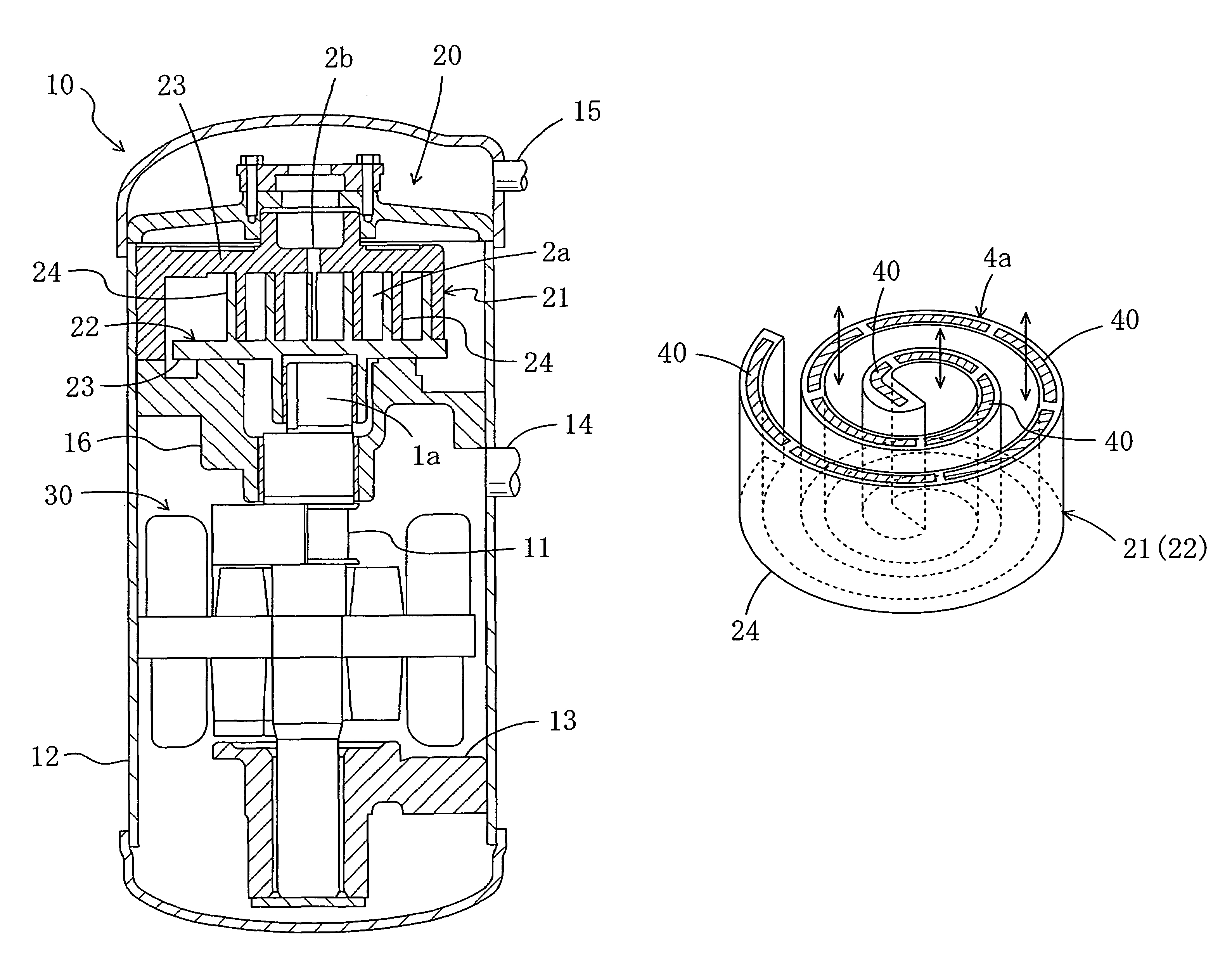
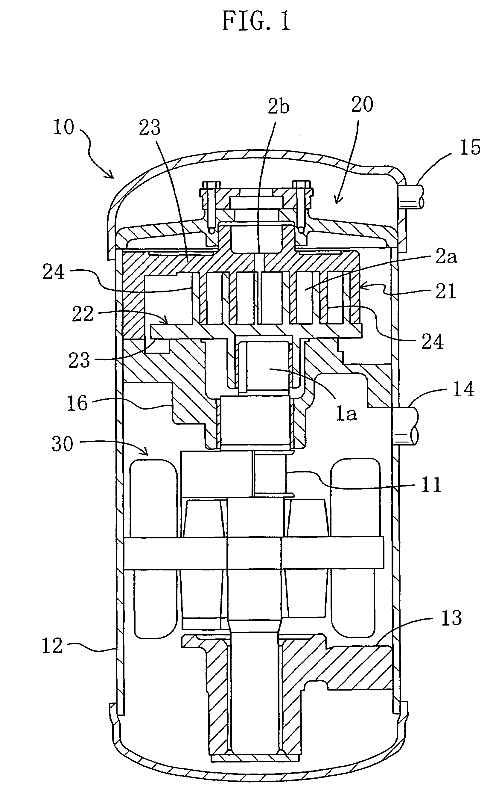
[0053]As shown in FIGS. 1 and 2A to 2D, a scroll fluid machine of the present embodiment is a scroll compressor (10). The scroll compressor (10) includes a compressor mechanism (20), a motor (30) and a drive shaft (11). The scroll compressor (10) is incorporated in a refrigerant circuit such as an air conditioner to compress refrigerant gas.

[0054]The motor (30) is connected to the compressor mechanism (20) via the drive shaft (11). The compressor mechanism (20) and the motor (30) are hermetically disposed in a cylindrical casing (12). The scroll compressor (10) is vertically oriented. The compressor mechanism (20) is positioned at an upper part of the inside space of the casing (12) and a bottom bearing (13) is positioned at a lower part of the inside space of the casing (12). The motor (30) is arranged between the compressor mechanism (20) and the bottom bearing (13).

[0055]The casing (12) further includes a suction pipe (14) provided between the compressor mechanism (20) and the mo...

second embodiment

[0089]Hereinafter, a detailed explanation of the second embodiment will be provided with reference to FIG. 6.

[0090]Different from the polymer actuators (40) of the first embodiment which are configured to change their shapes along the height, the polymer actuators (40) of the present embodiment change their shapes in the circumferential direction.

[0091]Specifically, as indicated by the arrows in FIG. 6, the polymer actuators (40) are configured to change their shapes along the spiral of the wrap (24).

[0092]If all the polymer actuators (40) reach the maximum length during the compression of the refrigerant, gaps between the polymer actuators (40) are minimized, thereby maximizing the compression capacity. If the length of the polymer actuators (40) is reduced from the maximum level at which the capacity is at the maximum, the gaps between the polymer actuators (40) increase, thereby increasing the amount of the space between the end plate (23) and the wrap (24). As a result, the amou...

third embodiment

[0099]A detailed explanation of a third embodiment of the present invention will be provided with reference to FIG. 7.

[0100]Different from the polymer actuator (40) of the first embodiment which also functions as a seal, the polymer actuator (40) of the present embodiment is separated from the seal.

[0101]Specifically, a sealing element (50) is provided on each of the polymer actuators (40) such that the sealing element (50) contacts the end plate (23).

[0102]According to the structure, the wrap (24) and the end plate (23) are sealed with reliability and damage to the polymer actuators (40) is surely prevented.

[0103]Other components and the effect of the present embodiment are the same as those of the first embodiment.


PUM


Abstract

A scroll fluid machine includes a stationary scroll having a spiral wrap formed on an end plate and a moving scroll having a spiral wrap formed on an end plate. A polymer actuator for adjusting the amount of space between the wrap and the end plate is disposed in a recess formed at a tip of the wrap. The polymer actuator changes its shape along a height of the wrap to adjust an amount of the space. The polymer actuator also functions as a seal between the end plate and the wrap. The recess is formed such that a wall of the recess including an inner circumference surface of the wrap has a thickness different from that of a wall of the recess including an outer circumference surface of the wrap.

Description

CROSS-REFERENCE TO RELATED APPLICATIONS[0001]This U.S. National stage application claims priority under 35 U.S.C. § 119(a) to Japanese Patent Application No. 2003-398642, filed in Japan on Nov. 28, 2003, the entire contents of which are hereby incorporated herein by reference.TECHNICAL FIELD[0002]The present invention relates to a scroll fluid machine, particularly to measures for controlling capacity.BACKGROUND ART[0003]Scroll compressors are conventionally incorporated in air conditioners. Having a fixed compression ratio, the scroll compressor is equipped with a power conditioning circuit such as an inverter to control the number of revolutions, thereby controlling the capacity.[0004]However, the provision of the power conditioning circuit brings about a problem of a significant cost increase. Further, the power conditioning circuit consumes a large amount of power and the efficiency decreases due to power loss by the inverter.[0005]In view of the above problem, Japanese Unexamin...

Claims


Application Information

Patent Timeline
Patent Type & Authority Patents(United States)
IPC IPC(8): F03C2/00F04C2/00F04C18/02F04C18/08F04C27/00F04C28/26
CPCF04C18/0284F04C18/084F04C27/005F04C28/265F05C2251/08
Inventor MASUDA, MASANORIHIGASHI, HIROFUMISAKITANI, KATSUMI
Owner DAIKIN IND LTD
Why Eureka
Try Eureka