
Power consumption estimation

a technology of power consumption and power consumption estimation, applied in the direction of transmission monitoring, line-transmission details, instruments, etc., can solve the problems of not being able to measure current consumption for a portion of an integrated circuit, requiring extra circuitry,

Inactive Publication Date: 2008-04-22
NXP USA INC
View PDF7 Cites 3 Cited by
  • Summary
  • Abstract
  • Description
  • Claims
  • Application Information

AI Technical Summary

Benefits of technology

The present invention relates to a system for estimating the power consumption of an integrated circuit. The invention provides a method for accurately estimating the power consumption of a circuit in real-time, without the need for extra circuitry or measuring current consumption. The invention uses a discrete time transfer function to map the input activity of a circuit to the power consumption of the circuit. The invention can be used in electronic systems to estimate the power consumption of a circuit in real-time. The technical effect of the invention is to provide a more efficient and accurate way to estimate power consumption of integrated circuits.

Problems solved by technology

However such a method requires extra circuitry.
Furthermore, it may not be possible to measure current consumption for a portion of an integrated circuit.

Method used


Image

  • Power consumption estimation
  • Power consumption estimation
  • Power consumption estimation

Examples


Embodiment Construction

[0015]The following sets forth a detailed description of a mode for carrying out the invention. The description is intended to be illustrative of the invention and should not be taken to be limiting.

[0016]An impulse response is the consequence of an event over time. A transfer function can be used to represent an impulse response. A power impulse response of an assertion (or other power consuming activity) of a signal at an input of a circuit represents the power consumed by a circuit over time due to the assertion of that signal. A power transfer function can be used to represent the power consumed over time by the assertion of the signal.

[0017]FIG. 1 sets forth a discrete time transfer function and table illustrating concepts of how a transfer function can be used for power consumption estimation of a circuit. Equation 101 is an example of a discrete transfer function which maps activity of groups of one or more input (e.g. g1, g2) of a circuit (not shown) to the total power consu...


PUM


Abstract

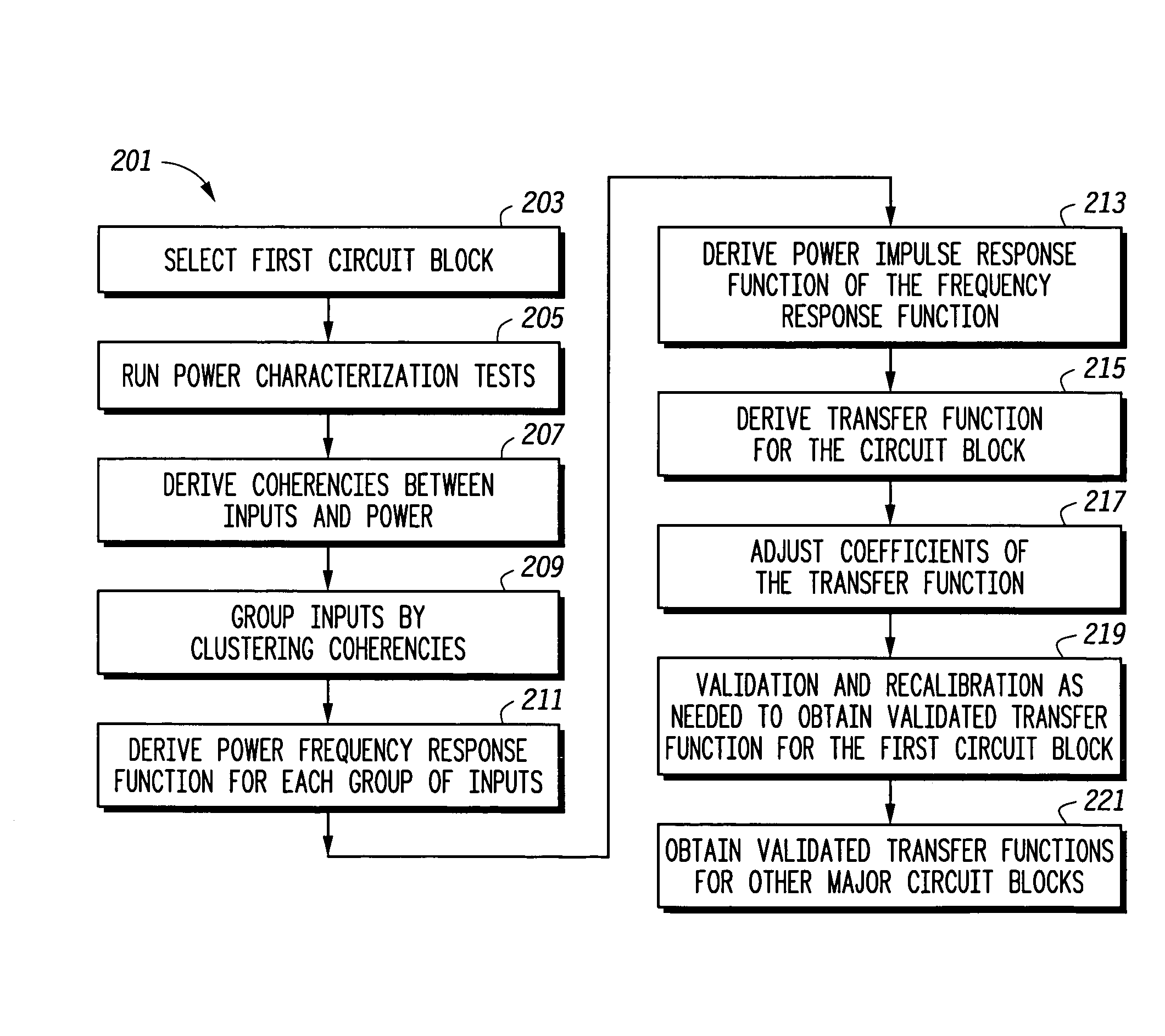
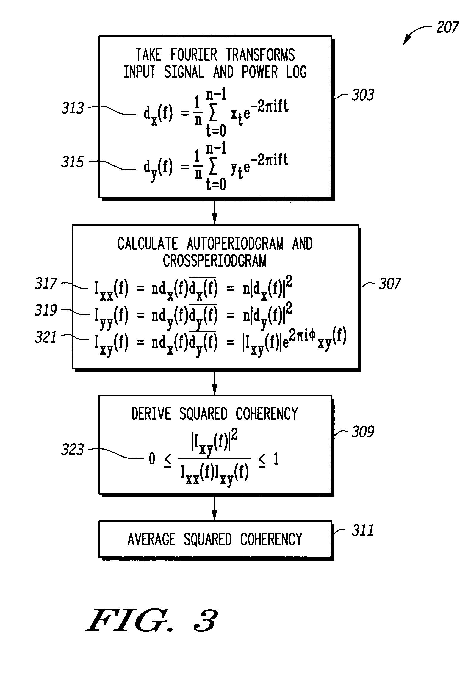
A process for deriving a power transfer function of a circuit. The power transfer function can be used to represent the real time power consumption of a circuit based on the status of the inputs. In one embodiment, the power transfer function is derived from frequency domain analysis of signals applied to the inputs of a circuit during tests of the circuit. In one embodiment, the inputs of the circuit are grouped in groups based on a commonality of power consumption of the signals. The inputs may be grouped by clustering squared coherencies associated with the inputs. The transfer function may be implemented in a power monitoring circuit having inputs coupled to the inputs of the circuit to provide a real time estimation of power consumption of the circuit.

Description

BACKGROUND OF THE INVENTION[0001]1. Field of the Invention[0002]This invention relates in general to integrated circuits and more specifically to power usage estimation for integrated circuits.[0003]2. Description of the Related Art[0004]It may be desirable for some applications to have a real time estimate of power consumption of an integrated circuit or of a portion of an integrated circuit. Power consumption may be measured by measuring the amount of current being consumed. However such a method requires extra circuitry. Furthermore, it may not be possible to measure current consumption for a portion of an integrated circuit.[0005]What is desirable is a system to provide a real time estimate of power consumption for at least a portion of a circuit.BRIEF DESCRIPTION OF THE DRAWINGS[0006]The present invention may be better understood, and its numerous objects, features, and advantages made apparent to those skilled in the art by referencing the accompanying drawings.[0007]FIG. 1 se...

Claims


Application Information

Patent Timeline
Patent Type & Authority Patents(United States)
IPC IPC(8): G06F17/50H04B3/46
CPCG06F1/28G06F17/5009G06F2217/78G06F30/20G06F2119/06
Inventor CAO, LIPENG
Owner NXP USA INC
Learn More