Coffee roaster having an apparatus for increasing airflow in a roasting chamber

a technology for roasters and coffee, which is applied in the field of roaster having an apparatus for increasing airflow in the roasting chamber, can solve the problems of coffee enthusiasts, roasters, and coffee being over or underroasted, and achieve the effect of increasing the speed of airflow

Inactive Publication Date: 2008-04-22
NUWAVE
View PDF17 Cites 3 Cited by
  • Summary
  • Abstract
  • Description
  • Claims
  • Application Information

AI Technical Summary

Benefits of technology

[0006]The present invention is directed to a roaster for roasting coffee beans and includes a roasting chamber having a top and a bottom. A cover is seated on the top of the roasting chamber and a bottom of the roasting chamber is seated on a base. A hot air supply is provided in the base for supplying hot airflow into the roasting chamber for heating the coffee beans. At least one air opening is formed on the bottom for enabling the airflow to enter the roasting chamber. A wind tunnel is provided over the air opening for increasing the speed of the airflow in the roasting chamber as the airflow passes through the wind tunnel.

Problems solved by technology

As a result, roasting coffee beans at a constant temperature for a prescribed time, as in conventional coffee roasters, do not always result in consistent and fully developed flavor that coffee enthusiasts desire.
These roasters, however, do not have the means for maintaining the desired roasting temperature when the ambient temperature varies.
In such a situation, the temperature inside the roasting chamber may not be at the desired temperatures, resulting in the beans being over or under roasted.
Consequently, the noise level generated by the coffee roaster can be of nuisance.
On the other hand, coffee roasters with motors that operate at low RPM have a low noise level and may increase motor life.
However, the airflow generated by these roasters is sufficient to mix and roast only a small amount of coffee beans.
Another disadvantage of known roasters is that they generate uncomfortable amount smoke.

Method used


Image

  • Coffee roaster having an apparatus for increasing airflow in a roasting chamber
  • Coffee roaster having an apparatus for increasing airflow in a roasting chamber
  • Coffee roaster having an apparatus for increasing airflow in a roasting chamber

Examples


Embodiment Construction

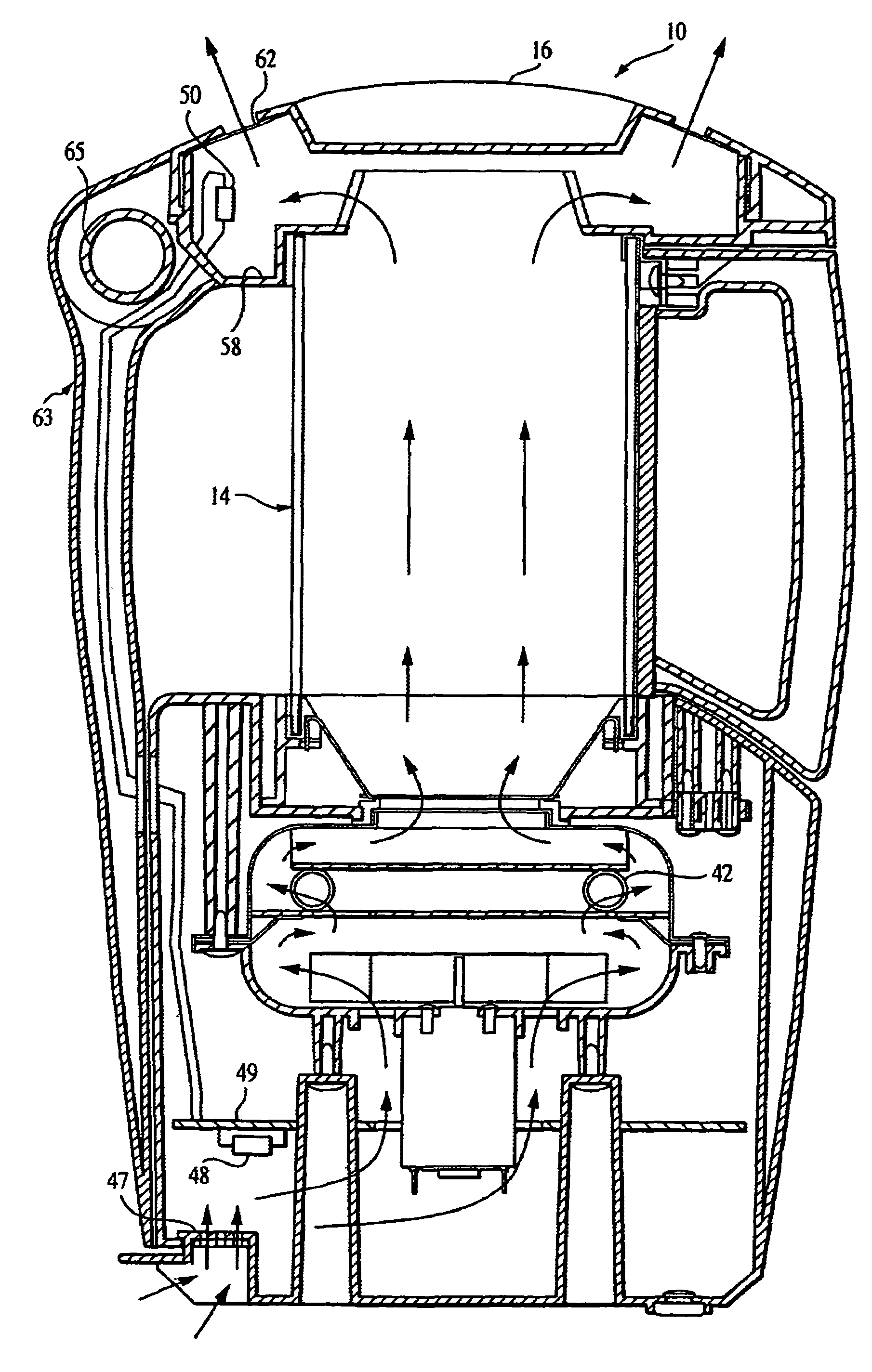
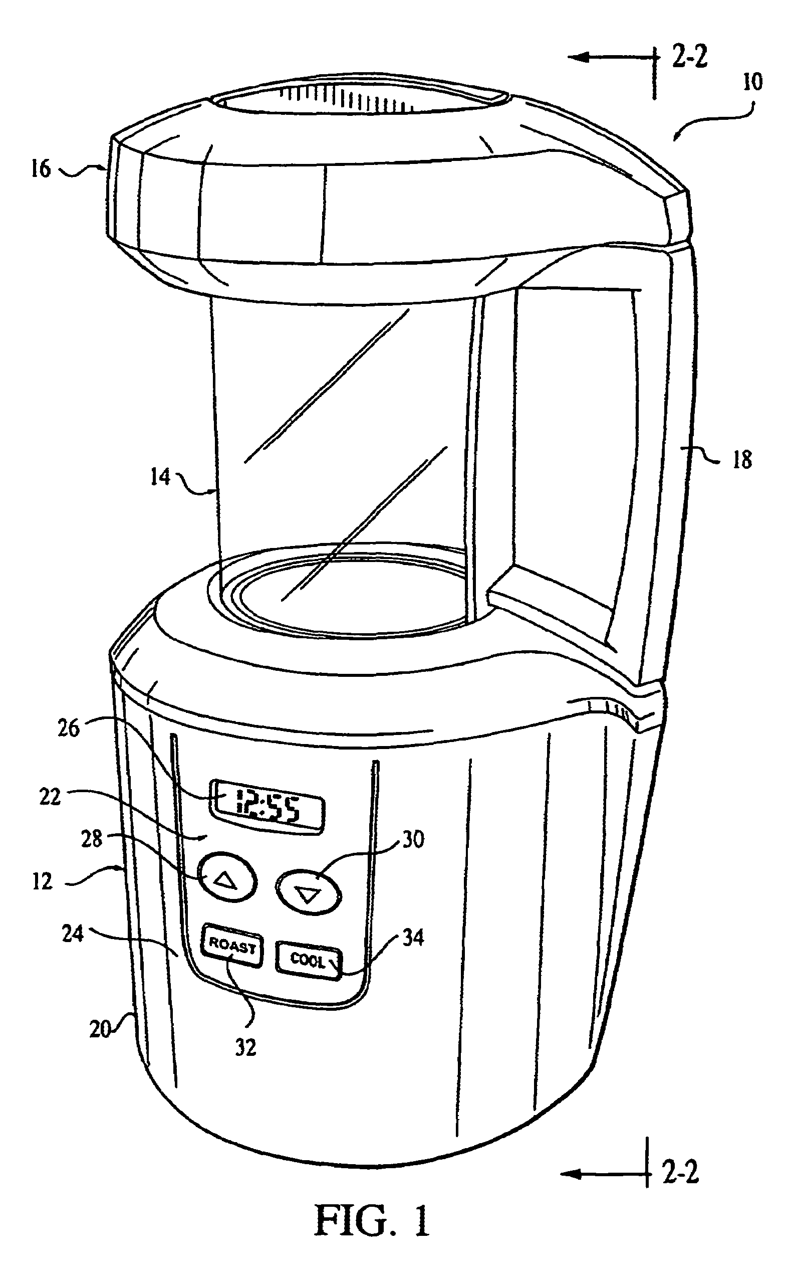
[0021]Turning now to FIG. 1, a coffee roaster in accordance with an embodiment of the present invention is indicated generally at 10, and includes a base 12, a generally cylindrical roasting chamber 14 seated in the base 12, and a cover 16 removably enclosing the roasting chamber at the opposite end from the base. A handle 18 is attached to the roasting chamber 14 to enable the roasting chamber to be removed from the base 12, and keep the roasting chamber steady while the cover 16 is being removed from or put on the roasting chamber.

[0022]The base 12 includes a housing 20 which is made preferably of light-weight plastic material. A control panel 22 is provided on a side 24 of the housing and includes a timer display 26 that shows the time remaining in the roasting process. The time can be adjusted by an UP switch 28 to increase the roasting time and a DOWN switch 30 to decrease the roasting time. The initial time, however, is set automatically to a preset time when the coffee roaste...


PUM


Abstract

A roaster for roasting coffee beans includes a roasting chamber having a top and a bottom. A cover is seated on the top of the roasting chamber and a bottom of the roasting chamber is seated on a base. A hot air supply is provided in the base for supplying hot airflow into the roasting chamber for heating the coffee beans. At least one air opening is formed on the bottom for enabling the airflow to enter the roasting chamber. A wind tunnel is provided over the air opening for increasing the speed of the airflow in the roasting chamber as the airflow passes through the wind tunnel.

Description

[0001]This application is a continuation-in-part of prior application Ser. No. 10 / 137,671, filed May 2, 2002, now U.S. Pat. No. 6,770,315.[0002]The present invention generally relates to coffee roasters, and more particularly to a coffee roaster that has a wind tunnel for increasing the speed of airflow in the roasting chamber without a corresponding RPM increase in the motor that creates the airflow, and a vent attachment for directing smoke from the roasting coffee beans away from the roaster.BACKGROUND[0003]A demand for coffee roasters for home use has been on the rise in response to growing number of devoted coffee drinkers who desire the flavor of freshly roasted coffee. These home coffee roasters typically have a heating element and a fan for directing hot air into a roasting chamber where the coffee beans are roasted as they are blown around by a hot air stream. The controls on these roasters typically include a variable timer that allows beans to be roasted at a constant tem...

Claims


Application Information

Patent Timeline
IPC IPC(8): A23N12/00A01J11/04A01J13/00A01J15/14A23B4/044A23L1/18A23N12/08A47J31/00F24C7/10F26B19/00F26B25/06
CPCA23N12/08A23N12/125
Inventor MOON, JUNG S.LIU, RONGCHAE, KITAKKIM, JONGROK
Owner NUWAVE
Why Eureka
Try Eureka