
Beam synthesis method for downlink beamforming in FDD wireless communication system

a wireless communication system and beam synthesis technology, applied in the field of wireless communication systems, can solve the problems of null-wrapping phenomenon, degrade the performance and capacity of downlink, and degrade the performance of the whole system, and achieve the effect of convenient, inexpensive and efficien

Inactive Publication Date: 2008-04-15
NAT UNIV OF SINGAPORE
View PDF13 Cites 26 Cited by
  • Summary
  • Abstract
  • Description
  • Claims
  • Application Information

AI Technical Summary

Benefits of technology

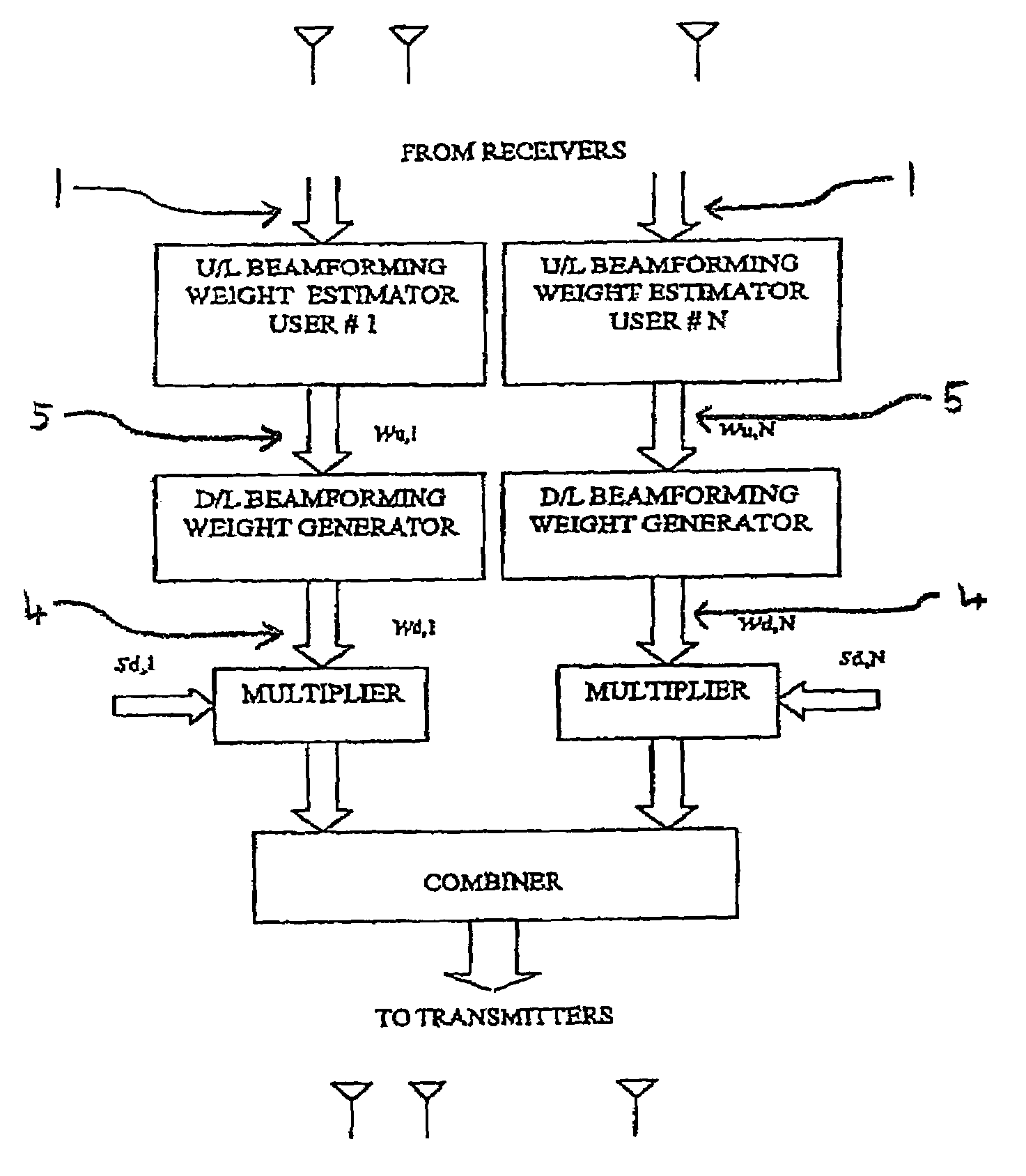
[0011]In uplink beamforming, real UBPCT is used to generate the optimal uplink beamforming weights by minimising the transmitted powers individually, and maximising the single-cell as well as multi-cell capacity. For FDD systems, if the uplink beamforming weights are used for downlink directly, not only the main beam, but also the nulls of the generated downlink beam pattern may have certain DOA shifts, which may greatly degrade the performance and capacity for downlink. By considering the similarity between real UBPCT for uplink and virtual UBPCT for downlink, for FDD systems, the generated uplink beam pattern using real UBPCT should be similar to the generated downlink beam pattern using virtual UBPCT, especially for the positions of main beam and nulls. Based on this observation, the present invention provides a beam synthesis (BES) method for generating downlink beamforming weights by modifying uplink beamforming weights directly. This method is simple in the sense that it does not require the downlink channel responses; also, no complicated computations, such as multi-variable optimization or matrix inversion, are involved.
[0017]The basic properties and benefits of the present invention are summarised as follows:1. The main concern complicating FDD systems is the lack of downlink channel vector estimates. The present invention does not require downlink channel responses for generating downlink beamforming weights.2. The present invention is simple for implementation as it does not require complicated computations nor large space for data storage.
[0027]Conveniently, the antenna spacing for the antenna array is selected to be less than or equal to half of the downlink wavelength, thereby avoiding the null wrapping phenomenon.
[0028]Advantageously, the antenna spacing for the antenna array is selected to be greater than half of the downlink wavelength and less than or equal to half the uplink wavelength, thereby alleviating the null-wrapping phenomenon.
[0038]an uplink receiver antenna array for receiving arriving signals from a plurality of remote terminals on respective uplink channels, the array having a predetermined antenna spacing to alleviate null-wrapping;

Problems solved by technology

For FDD systems, if the uplink beamforming weights are used for downlink directly, not only the main beam, but also the nulls of the generated downlink beam pattern may have certain DOA shifts, which may greatly degrade the performance and capacity for downlink.
In fact, the NC method may produce pseudo nulls for downlink due to FDD, incurring the null-wrapping phenomenon.
However, if the generated pseudo null is near the desired user's DOA, the generated downlink beam pattern's main beam will be destroyed, which may greatly degrade the performance of the whole system.
Such performance degrading nulls are termed bad nulls.

Method used


Image

  • Beam synthesis method for downlink beamforming in FDD wireless communication system
  • Beam synthesis method for downlink beamforming in FDD wireless communication system
  • Beam synthesis method for downlink beamforming in FDD wireless communication system

Examples


Embodiment Construction

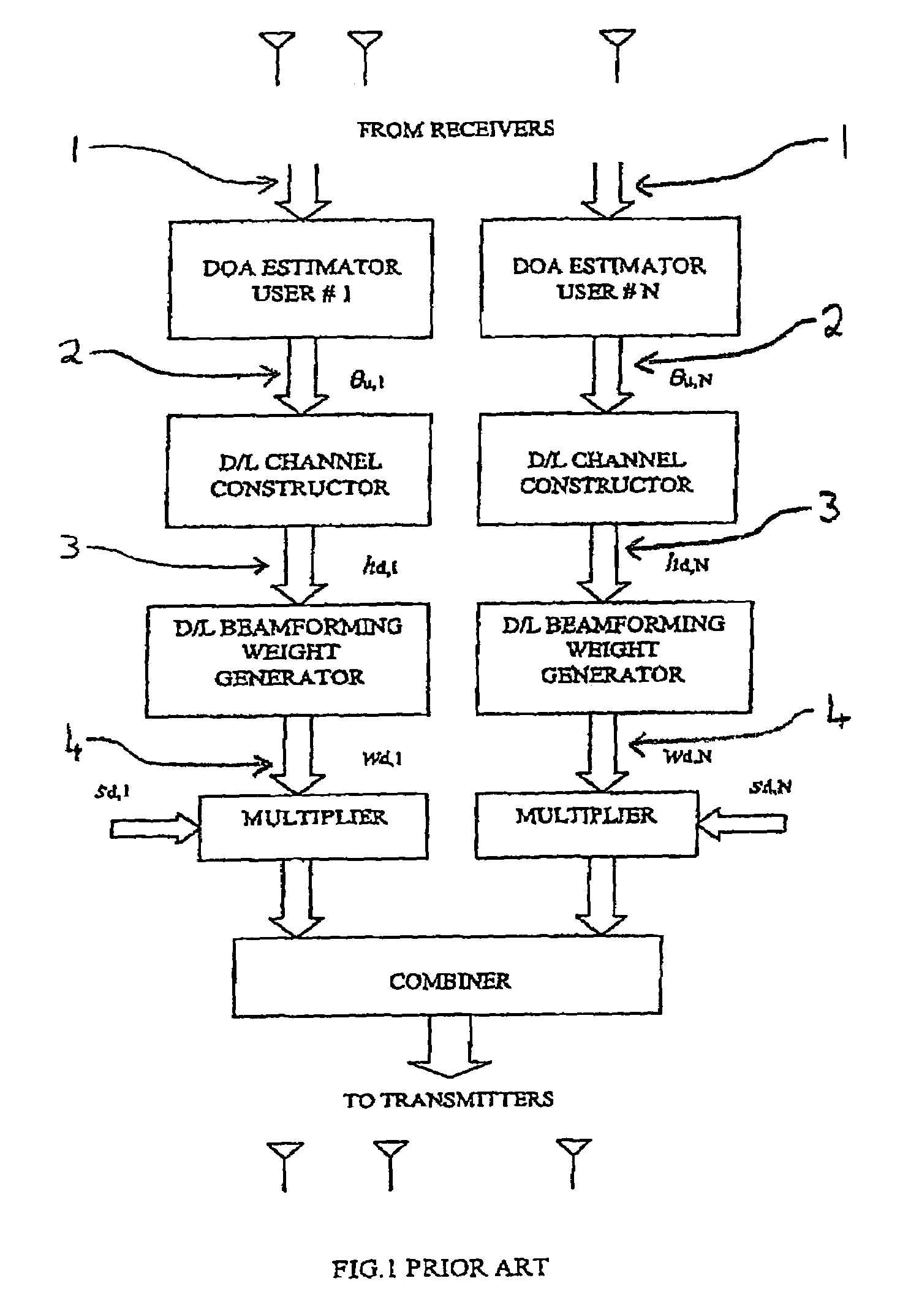
[0061]FIG. 1 shows the block diagram of a downlink beamforming scheme according to prior art for improving downlink performance and capacity using base station antenna array. A plurality of mobile users share the same channels which can be a time slot for TDMA, a frequency band for FDMA or a set of spreading codes for CDMA. Using a plurality of transceivers, higher system capacity and better transmission performance can be achieved if proper uplink and downlink beamforming schemes are employed.

[0062]The prior art systems first estimate each user's DOA values 2 from the received uplink signals 1, then construct the downlink channel responses (DCRs) 3 using downlink steering vectors for the estimated DOAs. Finally, the DCRs are set as the downlink beamforming vectors 4. As discussed in the first section of this application, the prior art system is very complicated in the sense that all users' DOAs are to be estimated; also, this system cannot provide enough downlink capacity to match ...


PUM


Abstract

A method for downlink beamforming in a frequency-division-duplex wireless communications system comprising a base station with an antenna array and terminals that are physically remote from said base station, the method comprising the steps of: receiving at said base station antenna array combinations of arriving uplink signals from said plurality of remote terminals, estimating an uplink beamforming weight vector for each of said terminals from said combinations of arriving uplink signal; identifying uplink nulls and an uplink main beam position from said uplink beamforming weight vector; transforming each of said uplink nulls to form a corresponding downlink null; generating a downlink beamforming weight vector from all downlink nulls; and transmitting a set of information signals from said base station antenna array according to said downlink. beamforming weights.

Description

BACKGROUND OF THE INVENTION[0001]The present invention relates in general to wireless communication systems and, more particularly, to using antenna array and signal processing techniques to increase downlink capacity and performance of wireless communication systems. The present invention relates to a new technique for generating downlink beamforming weights for frequency division-duplex (FDD) communication systems, which may include time division multiple access (TDMA), frequency division multiple access (FDMA), code division multiple access (CDMA) and their combinations.[0002]The next generation of wireless mobile communication systems will be required to provide a variety of services including digital voice, video and data in different transmission modes. These services will require high rate data transmission and high received signal power level, thus creating increased interference among users. In order to obtain high system capacity and reliable transmission quality, the inte...

Claims


Application Information

Patent Timeline
IPC IPC(8): H01Q3/00H04M1/00H01Q3/26H04B7/06H04B7/08H04B7/26
CPCH04B7/0617H04B7/086
Inventor LIANG, YING-CHANGCHIN, FRANCOIS
Owner NAT UNIV OF SINGAPORE
Learn More