
Adaptive jitter buffer control

a buffer control and buffer technology, applied in the field of data transmission, can solve the problem of too large playout time offset, and achieve the effect of reducing the playout time offs

Active Publication Date: 2008-04-15
CIENA
View PDF5 Cites 96 Cited by
  • Summary
  • Abstract
  • Description
  • Claims
  • Application Information

AI Technical Summary

Benefits of technology

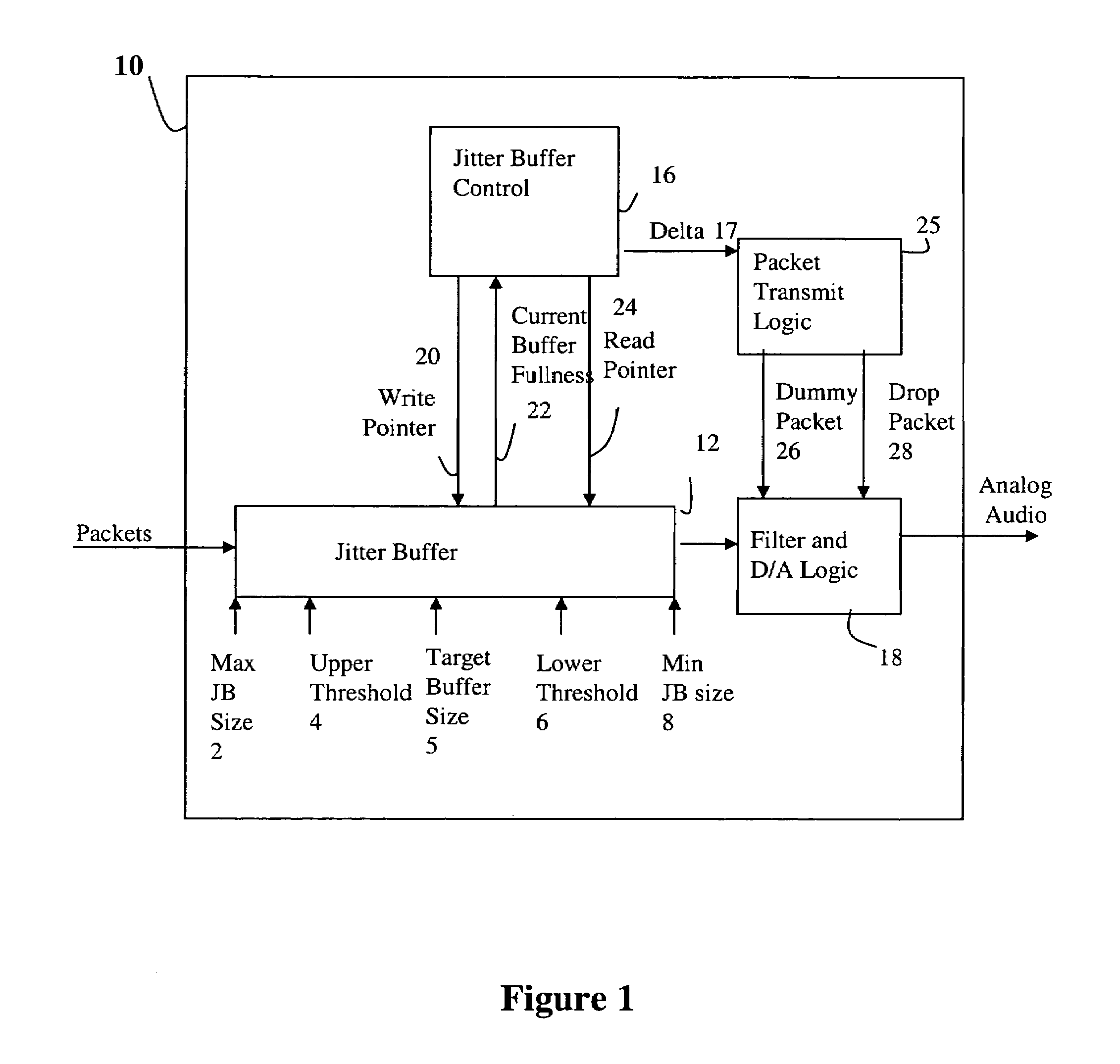
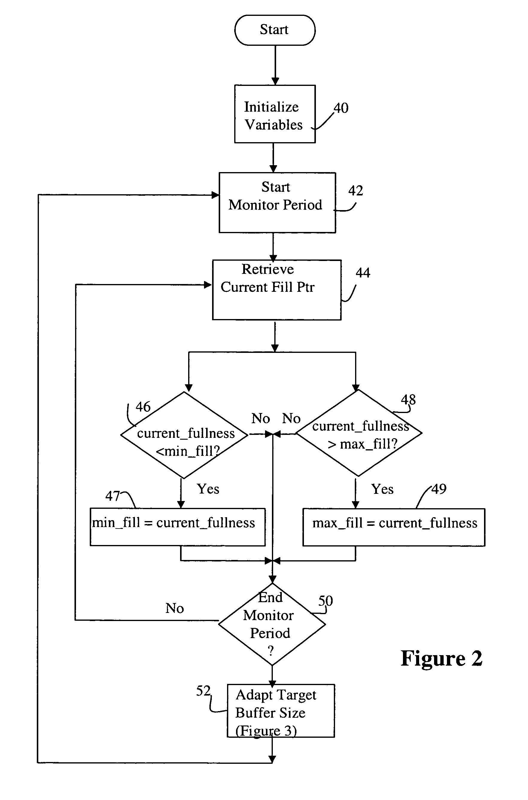
[0010]The present invention provides a method for dynamically adjusting jitter buffer size according to buffer fill dynamics. According to one embodiment, an upper threshold and lower threshold for the jitter buffer are identified, wherein the lower buffer threshold identifies a minimum desirable number of packets in the jitter buffer, and the upper buffer threshold identifies a maximum desirable number of packets in the jitter buffer. At any time, if the jitter buffer is only storing a number of packets that is below the lower threshold when it is time to play out a received packet sequence, then the time offset is considered too small. An adaptive controller causes dummy packets to be inserted in the output data stream to permit the jitter buffer to fill to a desirable level. If the buffer always has packets above the upper threshold, then the play out time offset is considered to be too large. The adaptive controller reduces the number of packets maintained in the buffer to below the threshold by discarding a number of packets at the head of the buffer or speeding up playout, thereby reducing the playout time offset. The ideal buffer size is somewhere between the two thresholds, and the adaptive algorithm ensures that the number of packets is within threshold bounds.

Problems solved by technology

If the buffer always has packets above the upper threshold, then the play out time offset is considered to be too large.

Method used


Image

  • Adaptive jitter buffer control
  • Adaptive jitter buffer control
  • Adaptive jitter buffer control

Examples


Embodiment Construction

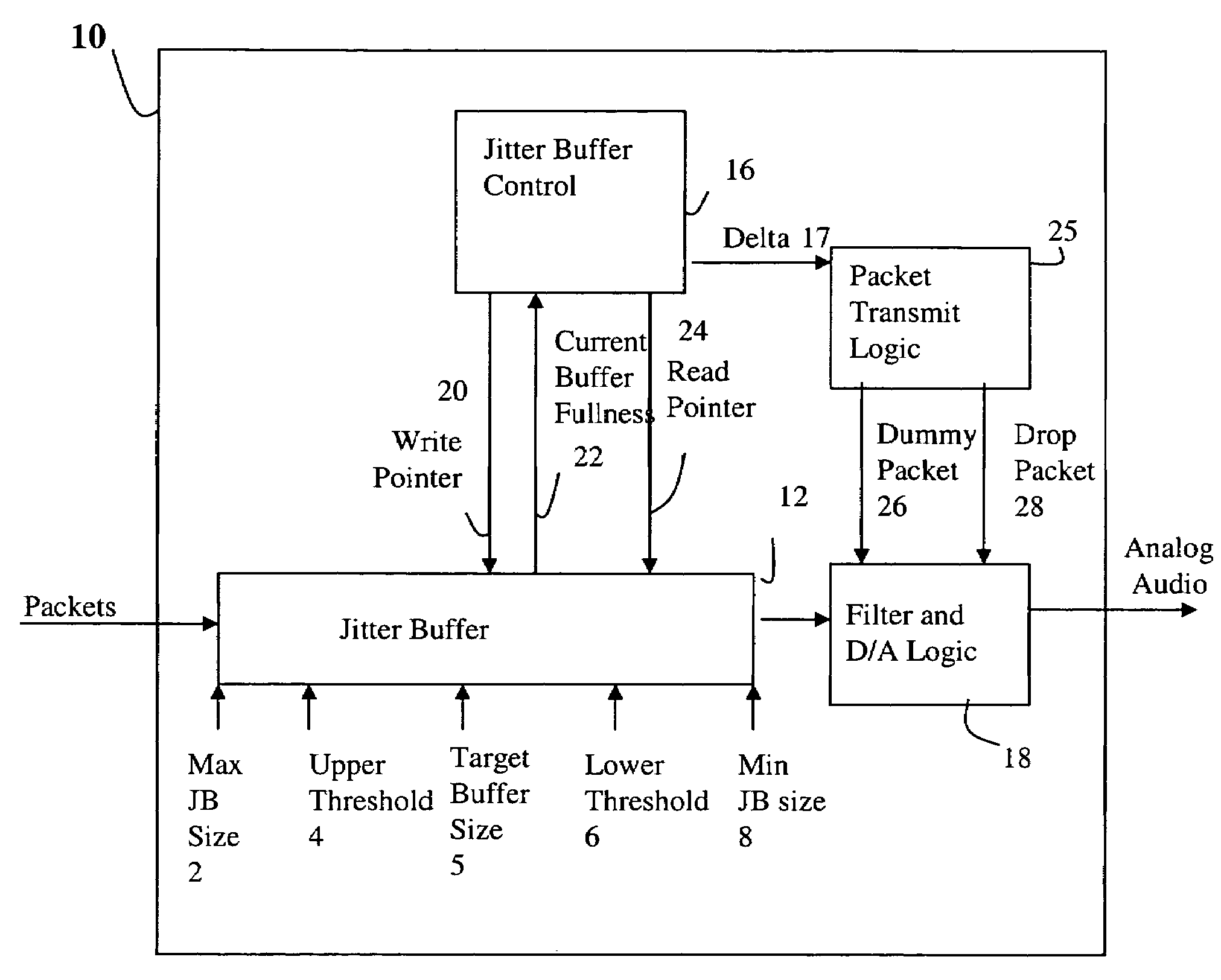
[0017]Referring now to FIG. 1, a block diagram of a device 10 that may be included in a receiver in a packet based network is shown. The embodiment described below will refer to packets that are received in a Voice Over Internet Protocol (VOIP) network device, however it should be appreciated that the below concepts may be expanded for use in any system whereby units of data are received at a device and it is desirable to monitor and update the characteristics of the buffer that stores the received units of data. Accordingly, the use of the terms ‘packet’ and VOIP network are exemplary only, and not a limitation of the present invention.

[0018]In addition, it should be noted that the attached description and drawings refer to several functional blocks or flow diagram steps that each perform a described function. The delineation of functionality between the blocks or steps has been described herein for exemplary purposes only, and it should be understood that the same functionality ma...


PUM


Abstract

A method for dynamically adjusting jitter buffer size according to buffer fill dynamics is disclosed. In one embodiment, an upper threshold and lower threshold for the jitter buffer are identified, wherein the lower buffer threshold identifies a minimum desirable number of packets in the jitter buffer, and the upper buffer threshold identifies a maximum desirable number of packets in the jitter buffer. Operating characteristics of the jitter buffer are monitored to identify instances when the jitter buffer size falls below or exceeds the desired thresholds. When a threshold is crossed, the adaptive algorithm alters the playback offset time, by introducing or deleting packets into the transmission path, to allow the jitter buffer size to return to a desirable target size within the threshold boundaries.

Description

FIELD OF THE INVENTION[0001]This invention relates generally to the field of data transmission and more particularly to a method and apparatus for maintaining a desired amount of data in a buffer.BACKGROUND OF THE INVENTION[0002]The goal of any communication system is to transmit real-time signals from one location to another. Currently, there are two types of networks that can be used to convey real-time media signals; circuit switched networks and packet switched networks. A circuit switched network provides a dedicated point to point communication path between two or more users. A media signal is transmitted over the dedicated circuit, received by the other side and played out to a user. A packet switched network, in contrast, divides a message to be sent into data packets, sent individually over the network, and reassembled at a final location before being delivered to a user. To ensure proper re-assembly of the blocks of data at the receiving end, various control data, such as ...

Claims


Application Information

Patent Timeline
Patent Type & Authority Patents(United States)
IPC IPC(8): H04L12/26
CPCH04L43/087H04L43/0852
Inventor OUELLETTE, MICHELMONTUNO, DELFINAWEYA, JAMESFELSKE, KENT
Owner CIENA
Learn More