
Method and system for diverting wireless network communications

a wireless network and communication technology, applied in the field of private wireless networks, can solve the problems of unfavorable unfavorable work, and difficulty in locating and locating the right telephone, so as to improve the building coverage of wireless local area networks, improve work efficiency, and improve the effect of data ra

Inactive Publication Date: 2008-04-08
SPRINT SPECTRUM LLC
View PDF38 Cites 98 Cited by
  • Summary
  • Abstract
  • Description
  • Claims
  • Application Information

AI Technical Summary

Benefits of technology

"The patent text describes a private wireless network that can provide services to mobile stations that subscribe to both private and public wireless networks. The private network has a base station and a switching system, while the public network has a home location register and a public network serving system. The private network also has a private network subscriber database accessible by the switching system. The patent text also describes methods for handing off a mobile station from one network to another, providing voice mail indication, and providing call origination and termination services. The technical effects of the patent text include improved mobility management and flexibility in providing wireless services to mobile stations."

Problems solved by technology

However, the switches had to have a great deal of “intelligence” built into them to accomplish this.
This approach was unwieldy because a telecommunications provider needed to update the software and databases on all of its many switches in order to update services or add new services throughout its telecommunications network.
Such networks are “private” in that the subscribers are typically limited to employees of, or other individuals associated with, the enterprise.
However, many such WOTS systems require specialized telephones, so that a standard cellular or PCS telephone that can be used in a public wireless network may not work in a given WOTS system.
With many people routinely carrying a cellular or PCS telephone, requiring a different telephone to be used at work is a substantial inconvenience.
However, IS-94 is not designed to handoff calls between the private and public cellular systems.
The lack of handoff capability is a significant disadvantage.
Some wireless office systems, however, have some limited ability to allow users to move between the private and public cellular networks during the course of a call.
However, if a call is originated within the coverage area of the ROAMEO system, it may be dropped if the telephone leaves the ROAMEO coverage area.
A disadvantage with this configuration, however, is that many users may already have a cellular telephone for personal use and may be disadvantaged by having to use a separate “corporate mobile terminal” for business.
However, the Widergen approach of using the HLR / SCP to serve the corporate mobile terminals in both the private and public networks does not facilitate the application of separate business and personal services.
Another disadvantage with this configuration is that the wireless office system “is implemented as a private wireless system that operates according to the same standard as the public cellular system.” See Widergen, et al., ln.
Windergen's technique of using the HLR / SCP to control the transmission of communication services in both the public and private wireless network does not facilitate application of different standards either using a single mobile station or multiple stations.

Method used


Image

  • Method and system for diverting wireless network communications
  • Method and system for diverting wireless network communications
  • Method and system for diverting wireless network communications

Examples


embodiment 1

[0208]D. Wireless Local Area Network Controller Embodiment 1

[0209]In an exemplary embodiment, the communication-diverter system 2710 includes wireless local area network controller (WLAN controller) 2704. Referring to FIG. 27, the WLAN controller 2704 is shown comprising (i) a wired local area network server (wired-LAN server) 2705 coupled to (ii) a wireless access point 2758, and coupled to (iii) a WLAN subscriber profile store 2769.

[0210]The wireless access point 2758 provides base station functionality for the WLAN by providing access, over an air interface, for multiple WLAN subscriber mobile stations, e.g., WLAN subscriber's mobile stations 2764a and 2764b, onto the wireless local area network. The wireless access point 2758 may consist of a radio transceiver 2761, a wired-network interface 2763, and a bridging software application 2765 that conforms to the IEEE 802.11d bridging standard, or some other LAN-based wireless bridging standard.

[0211]In an 802.11 compliant WLAN, WLAN...

embodiment 2

[0227]E. Wireless Local Area Network Controller Embodiment 2

[0228]In another exemplary embodiment, the wireless local area network controller (WLAN controller) is configured as PBX server 2804 coupled to the wireless access point 2758, and coupled to the WLAN subscriber profile store 2767. Referring to FIG. 28, a simplified block diagram of such WLAN controller configuration is shown integrated into the communication-diverter system 2810. The simplified block diagram shown in FIG. 28 is similar to the simplified block diagram shown in FIG. 27, except as described herein.

[0229]The PBX server 2804 is coupled to the wireless access point 2758 via a shared media access mechanism, such as an Ethernet connection. The PBX server 2804 may communicate with the wireless access point 2758 using an IEEE 802.3 or other wired local area network (wired-LAN) protocol. Alternatively, the wireless access point functionality may be integrated into the PBX server 2804. The wireless access point functio...

embodiment 3

[0249]F. Wireless Local Area Network Controller Embodiment 3

[0250]In another exemplary embodiment, the wireless local area network controller (WLAN controller) is configured as VoP network server 2907 coupled to the wireless access point 2758, and coupled to the WLAN subscriber profile store 2767. Referring to FIG. 29, a simplified block diagram of such WLAN controller configuration is shown integrated into the communication-diverter system 2910. The simplified block diagram shown in FIG. 29 is similar to the simplified block diagram shown in FIG. 27, except as described herein.

[0251]In an exemplary embodiment, the VoP network server 2907 may encompass a wired local area network server (wired-LAN server) 2705, for instance, an IEEE 802.3 LAN server running a Voice-over Packet-data (VoP) application, such as a Voice-over-Internet Protocol (VoIP) application. The VoP, VoIP or other voice-over-packet-switched data network application provides telecommunication services over packet-swit...


PUM


Abstract

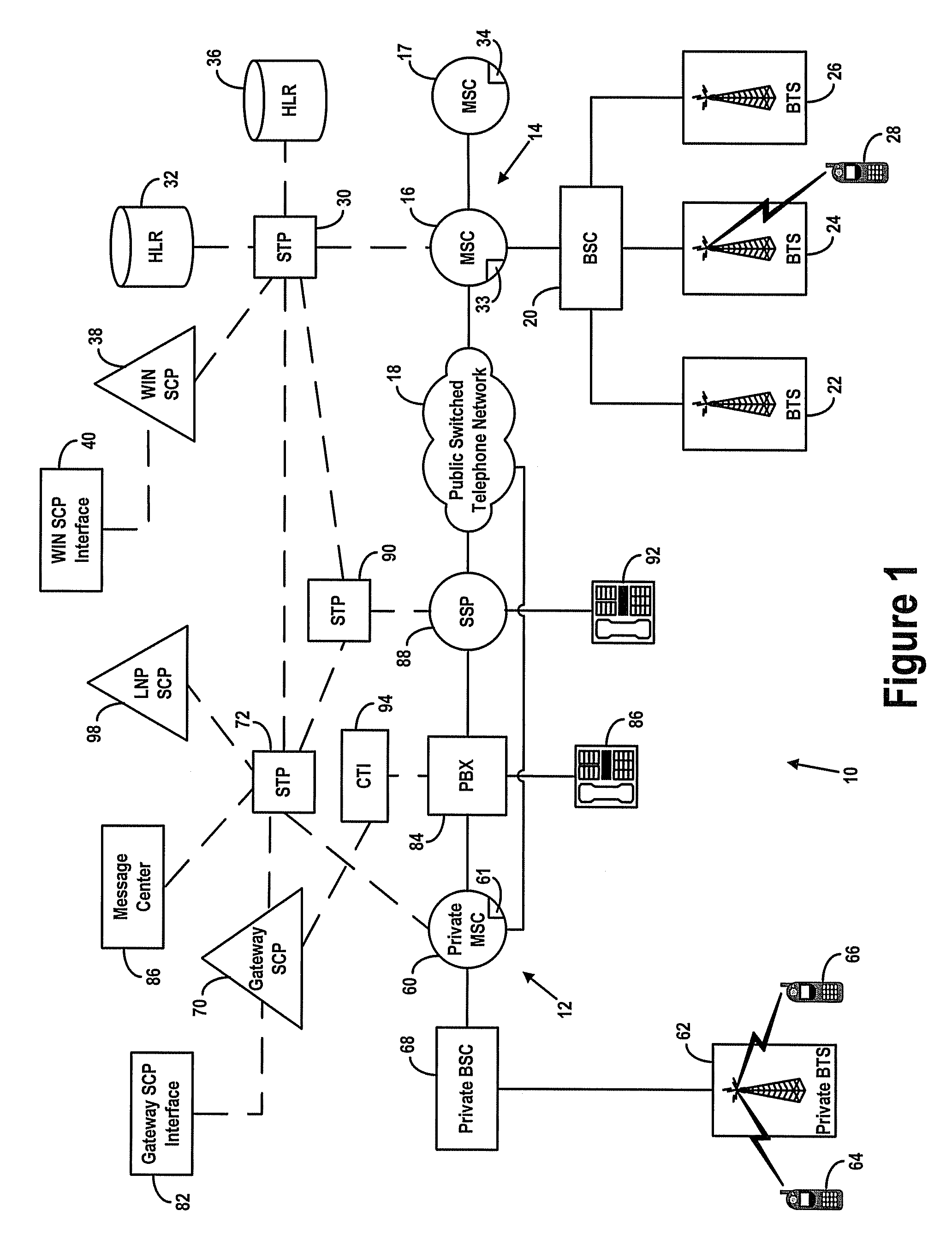
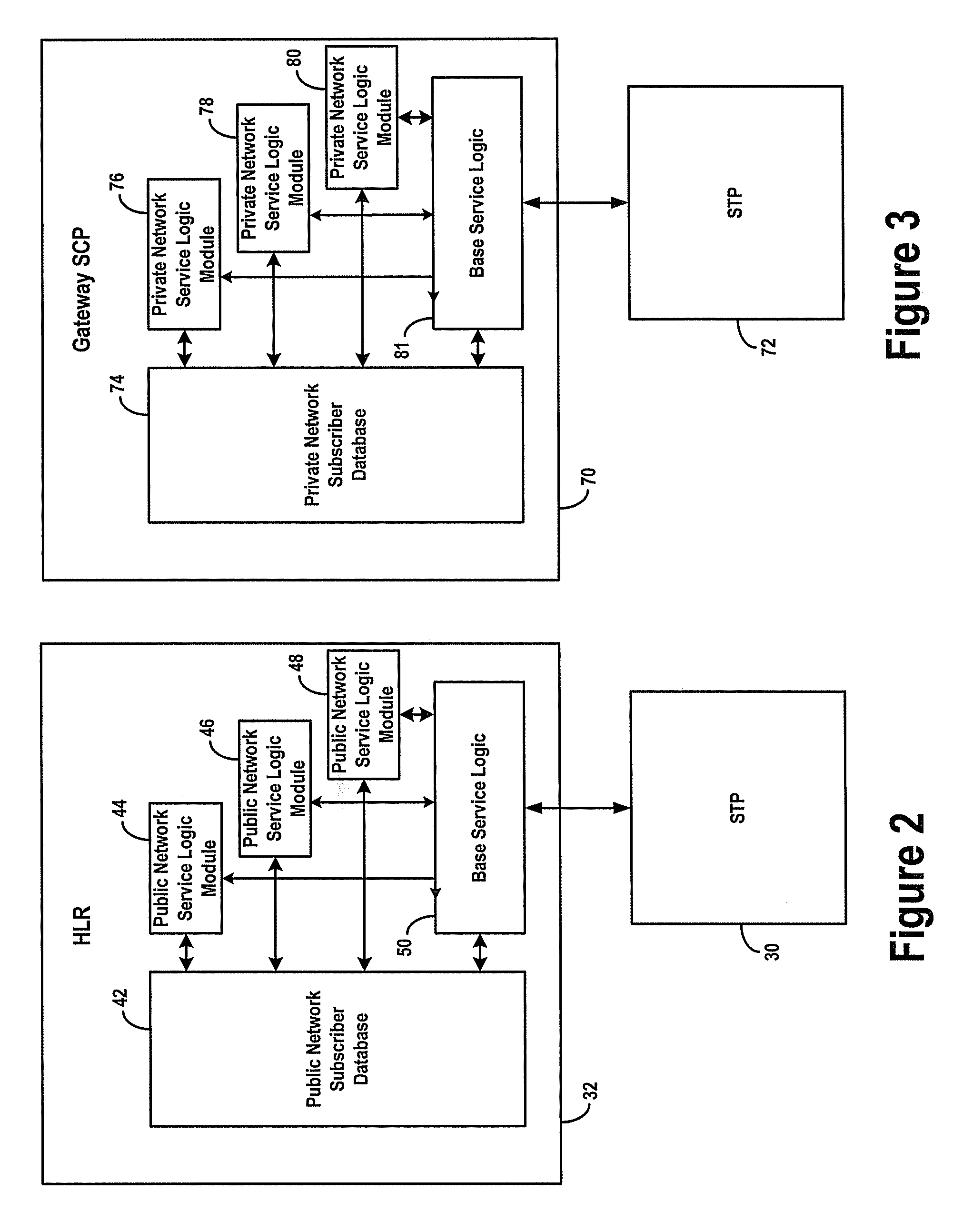
A private wireless network is able to provide wireless telecommunication services to subscriber mobile stations that also subscribe to a public wireless network. The private wireless network includes a private base transceiver station (BTS), a private mobile switching center (MSC), and a gateway service control point (SCP). The private BTS provides a private network wireless coverage area within which the mobile station can communicate with the base transceiver station over an air interface. The gateway SCP has a private network database containing private network data records for subscribing mobile stations. A private network data record includes a private network service profile and a private network locator address. The public wireless network has a home location register (HLR) with a public network database containing public network data records for subscribing mobile stations. A public network data record includes a public network service profile and a public network locator address. When a subscriber mobile station is active on the private wireless network, the private network locator address identifies the private MSC, and the public network locator address identifies the gateway SCP. By providing the private network wireless coverage area so that it overlaps the public network's wireless coverage area, the subscriber mobile station may be handed off between the private and public wireless networks.

Description

RELATED APPLICATIONS[0001]The present application is related to Non-provisional application Ser. No. 09 / 595,595, filed Jun. 15, 2000, titled “Private Wireless Network Integrated with Public Wireless Network,” which is assigned to the same assignee as the present application. The present application also claims priority under Title 35, United States Code §120 from the Non-provisional application Ser. No. 09 / 595,595, filed Jun. 15, 2000, titled “Private Wireless Network Integrated with Public Wireless Network.”BACKGROUND OF THE INVENTION[0002]1. Field of the Invention[0003]The present invention relates in general to telecommunications networks and more particularly to a private wireless network that is integrated with a public wireless network.[0004]2. Description of Related Art[0005]Recent advances in telecommunications technology have allowed a wide array of special telecommunication services to be made available to subscribers. Examples of such services include abbreviated dialing,...

Claims


Application Information

Patent Timeline
Patent Type & Authority Patents(United States)
IPC IPC(8): H04Q7/00H04B7/00H04B1/38H04W8/02H04W84/02H04W92/02H04W92/06
CPCH04W84/02H04Q2213/13093H04Q2213/13098H04Q2213/13103H04Q2213/13109H04Q2213/13166H04Q2213/13196H04Q2213/1322H04Q2213/1328H04Q2213/13292H04Q2213/13294H04Q2213/13345H04Q2213/13384H04W8/02H04W84/105H04W92/02H04W92/06
Inventor JONES, BRYCE A.DELKER, JASONMCCONNELL, VON K.
Owner SPRINT SPECTRUM LLC
Learn More