
Scene imaging system integrity monitor and method thereof

Active Publication Date: 2008-04-08
ROCKWELL COLLINS INC
View PDF8 Cites 30 Cited by
  • Summary
  • Abstract
  • Description
  • Claims
  • Application Information

AI Technical Summary

Benefits of technology

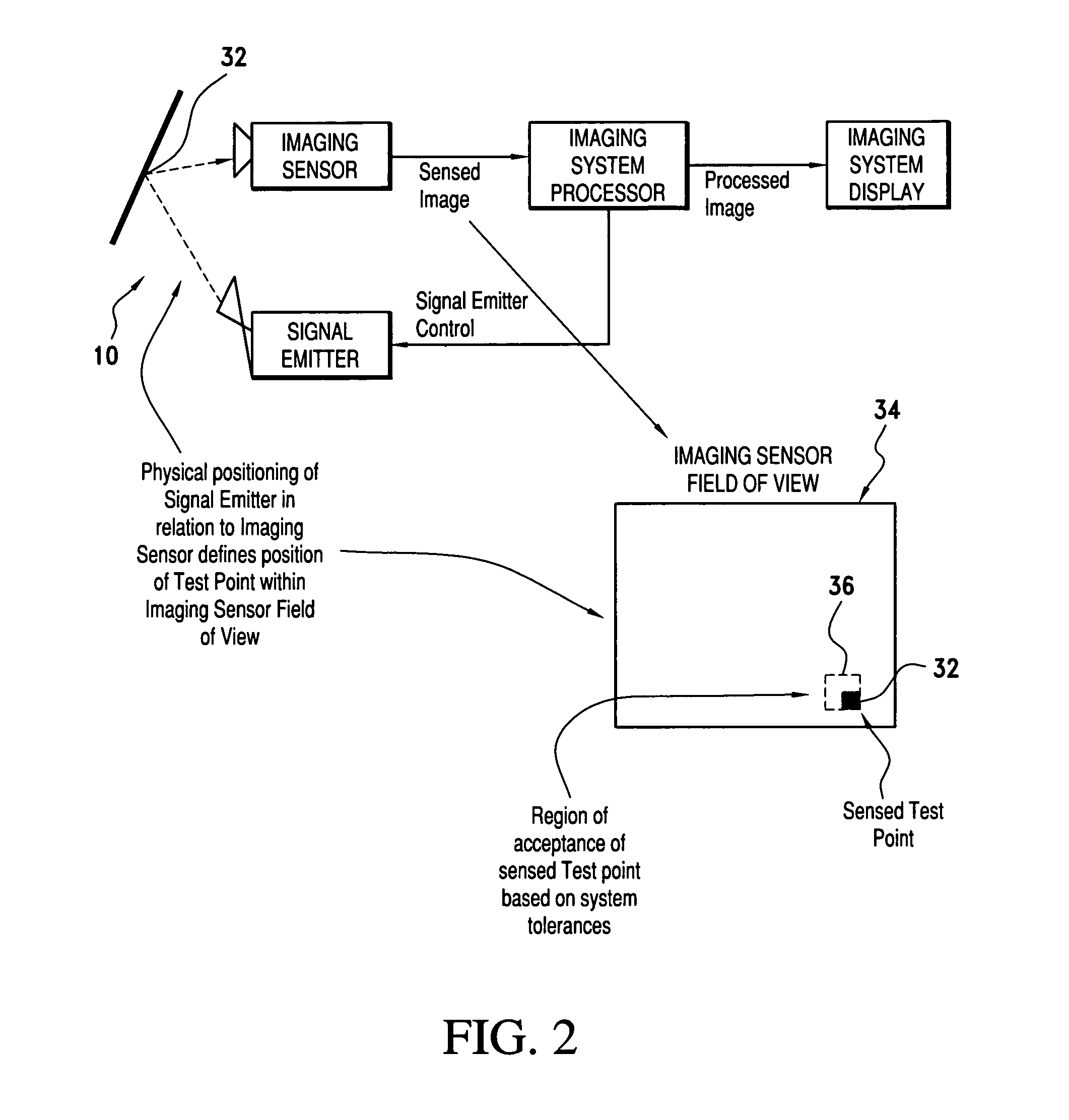
[0010]The advantage of this invention is that it allows for the assurance of the required operation of certain SIS functions through partially external means while not relying completely on SIS built-in test functions. In this instance, the SIS imaging sensor is allowed to operate normally without being forced into a special test state, while a test object is artificially introduced into the sensed image of the SIS imaging sensor. The test object, while controlled by the SIS, is generated from a source which is external to the SIS imaging sensor and, therefore, appears in the sensed image as any other object of the normal scene would. Detection, or the lack thereof, of the test object within a normally processed image defines the required operation of the SIS. Therefore, this monitoring technique allows the monitoring apparatus and functions to be added to the SIS without any modification to the SIS imaging sensor.

Problems solved by technology

The issue that often arises in the development process, if a process was followed at all, is due to minimal or nonexistent design and design and performance assurance documentation.

Method used


Image

  • Scene imaging system integrity monitor and method thereof
  • Scene imaging system integrity monitor and method thereof
  • Scene imaging system integrity monitor and method thereof

Examples


Embodiment Construction

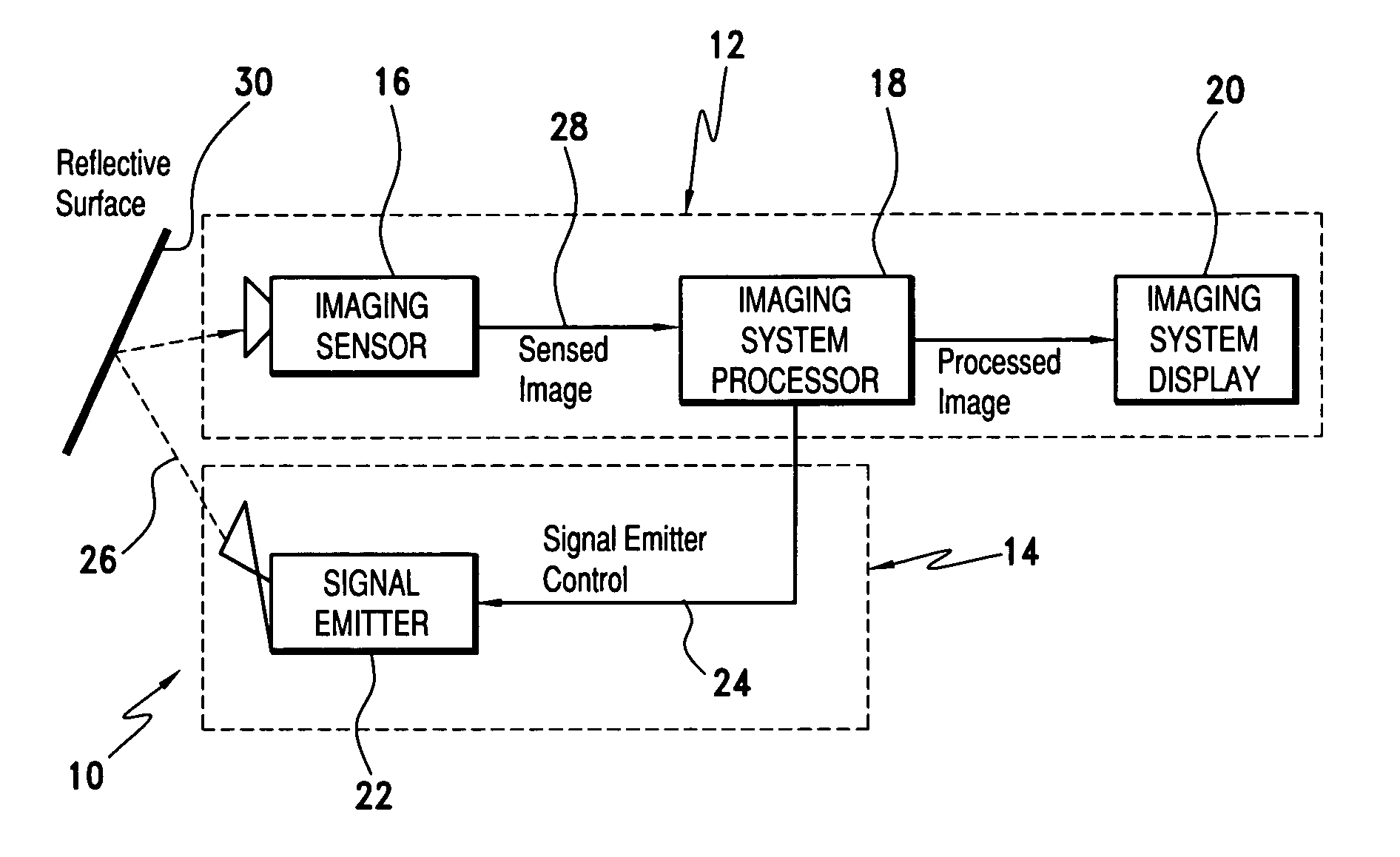
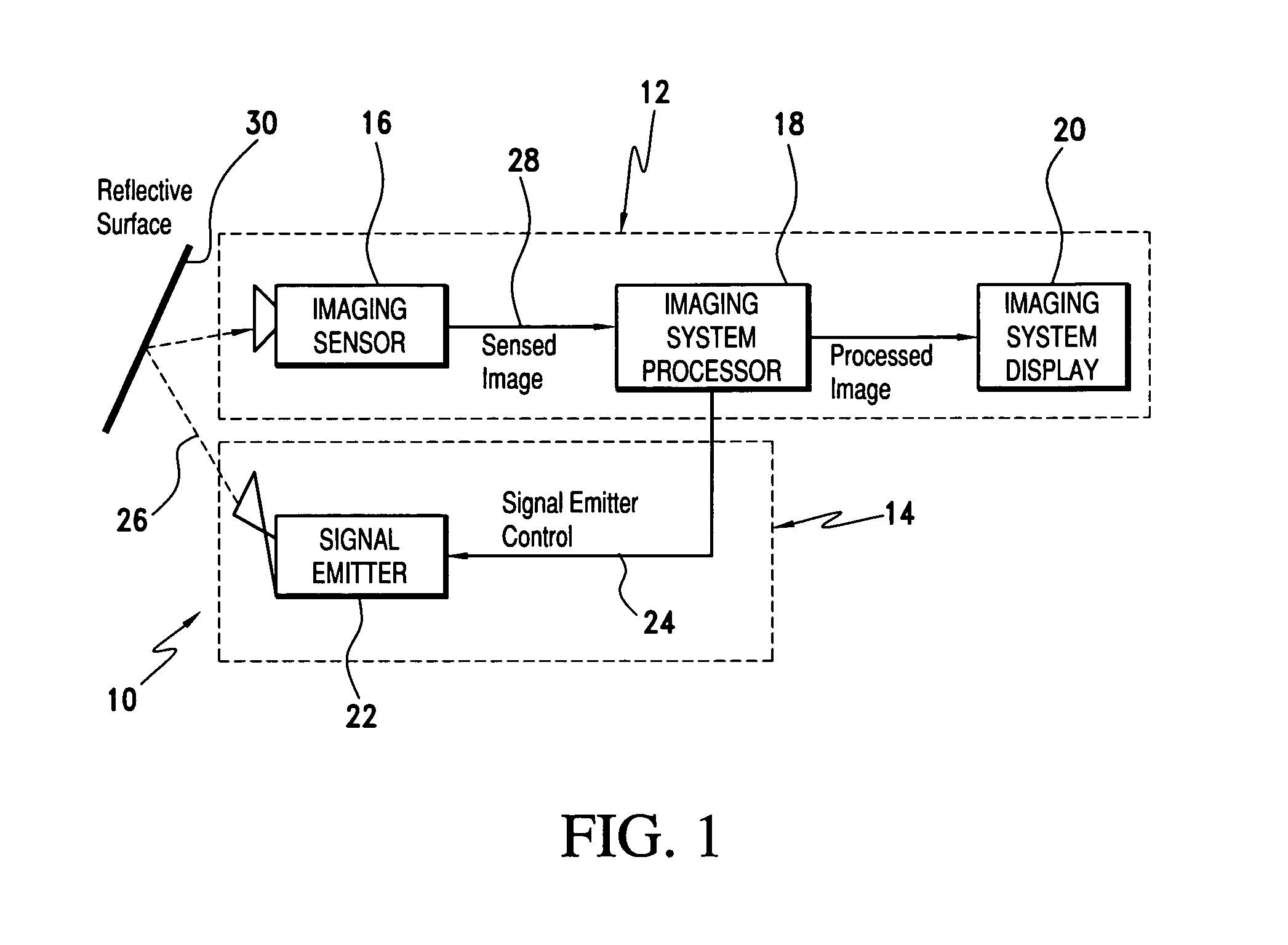
[0017]Referring now to the drawings and the characters of reference marked thereon, FIG. 1 illustrates a scene imaging / integrity monitoring (SI / IM) system 10 of the present invention. The SI / IM system 10 includes a scene imaging system (SIS) 12 and a scene imaging system (SIS) integrity monitor 14. The SIS 12 includes an imaging sensor 16, an imaging system processor 18, and an imaging system display 20. The SIS 12 may be for, example, an enhanced vision system (EVS) and include any number of scene imaging sensors, e.g. visible light, infrared, millimeter-wave radar, X-band (weather) radar, etc. Other types of SIS's may include, for example surveillance systems, fire detection systems, and imaging systems used for automated parts assembly.

[0018]The SIS integrity monitor 14 includes a signal emitter assembly 22 for receiving emitter drive signals 24 from the imaging system processor 18 and directs a monitoring image 26 into the active field of view of the imaging sensor 16 for sensed...


PUM


Abstract

A scene imaging system (SIS) integrity monitor for monitoring the required operation of an imaging sensor of an SIS. The SIS is of a type including: i) an imaging sensor, ii) an imaging system processor, and iii) an imaging system display. The SIS integrity monitor includes a signal emitter assembly for receiving emitter drive signals from an imaging system processor and directing a monitoring image into the active field of view of an imaging sensor for sensed image generation. The generated image is provided to the imaging system processor for analysis. The imaging system processor evaluates the location and modulation state of the generated image to determine if faults exist in the image generation or image display paths.

Description

BACKGROUND OF THE INVENTION[0001]1. Field of the Invention[0002]The present invention relates to scene imaging systems and more particularly to a monitoring system for monitoring the required operation of an imaging sensor of the scene imaging system. The present monitoring system has particular application relative to monitoring an Enhanced Vision System (EVS) of an aircraft.[0003]2. Description of the Related Art[0004]Many devices, such as aircraft, are typically designed to provide a real-world view of the out-the-window scene for at least one operator to operate the device. In the past, a view of the scenery outside the device was provided through passive means, such as a cockpit windshield, or artificial means through sensors and displays.[0005]Enhanced Vision Systems (EVS) supplement out-the-window vision via the use of camera / sensor imagery superimposed over the real-world view. EVS include sensors that can detect and display images of objects that pilots would not normally b...

Claims


Application Information

Patent Timeline
IPC IPC(8): G01J5/02
CPCG06T1/00G06T7/001G06T2207/30252
Inventor WOOD, ROBERT B.WILSON, JOHN G.ZIMMERMAN, KENNETH A.
Owner ROCKWELL COLLINS INC
Learn More