
Structure of illuminating unit and structure of illuminating light source

a technology of illuminating units and light sources, applied in the field of illumination technology, can solve the problems of difficult to effectively lead the lights emitted in solid angle into a parallel beam, uneven intensity of emitted light, and non-uniform luminance of light-emitting devices

Inactive Publication Date: 2008-04-08
WALSIN LIHWA
View PDF8 Cites 17 Cited by
  • Summary
  • Abstract
  • Description
  • Claims
  • Application Information

AI Technical Summary

Benefits of technology

[0011]The invention provides a structure of illuminating unit, which can effectively lead the divergent light into a collimating light, and can have light mixture by reflection, at the same time. As a result, the effect of collimating and uniform light can be achieved.
[0012]The invention provides a structure of illuminating light source, which uses several illuminating units to form an array, so as to achieve the performance of planar light source. The devices in illuminating units are not densely arranged together, so that the conventional high temperature can be reduced. In addition, the illuminating units can be put together in good match, so that the gap region without emitting light between the adjacent two illuminating units is reduced.

Problems solved by technology

In addition, the light emitted from the emitting diode (LED) as the light source is distributed in full solid angle, and the intensity of emitted light is not uniform on each side, caused by the non-uniform distribution of the internal current density.
Further, the surface of the electrode also blocks the light, and clearly causes a light-emitting device with non-uniform luminance.
Furthermore, it is quite difficult to effectively lead the lights emitted in solid angle into a parallel beam as the collimating light.
Therefore, it is a big challenge to have a light source with high illuminating power, collimating, and uniform light.
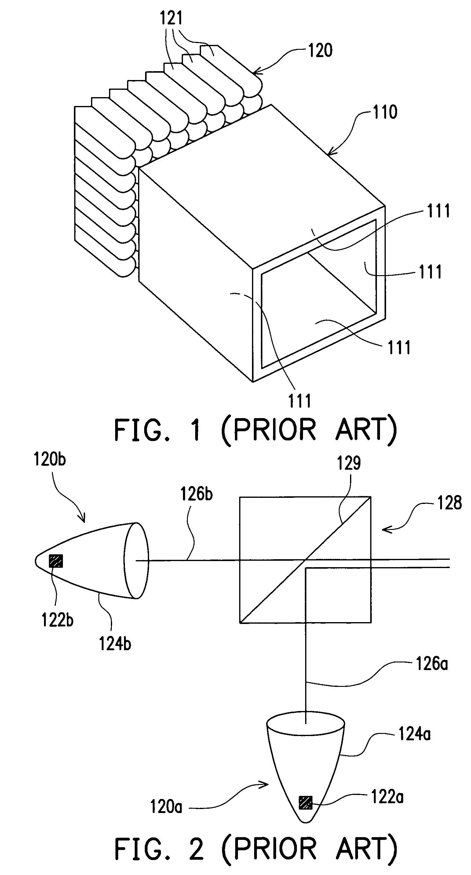
However, each of the light lamps has a non-uniform distribution of light intensity, symmetrical to a center axis.
This would severely cause a dark region and then a non-uniform light source with interleave between bright region and dark region.
In other words, even though the tube reflection structure is used, the mixing effect is still poor.
In this situation, the dense LEDs driven by high current would cause a high temperature, which further reduces the light-emitting efficiency.
The lights from LEDs are not uniform, and the light source is still non-uniform after passing the axial symmetric reflection mirror for collimating the light.
The foregoing conventional designs still have the disadvantages, such as non-uniform light intensity or affecting quality of light source due to high temperature.

Method used


Image

  • Structure of illuminating unit and structure of illuminating light source
  • Structure of illuminating unit and structure of illuminating light source
  • Structure of illuminating unit and structure of illuminating light source

Examples


Embodiment Construction

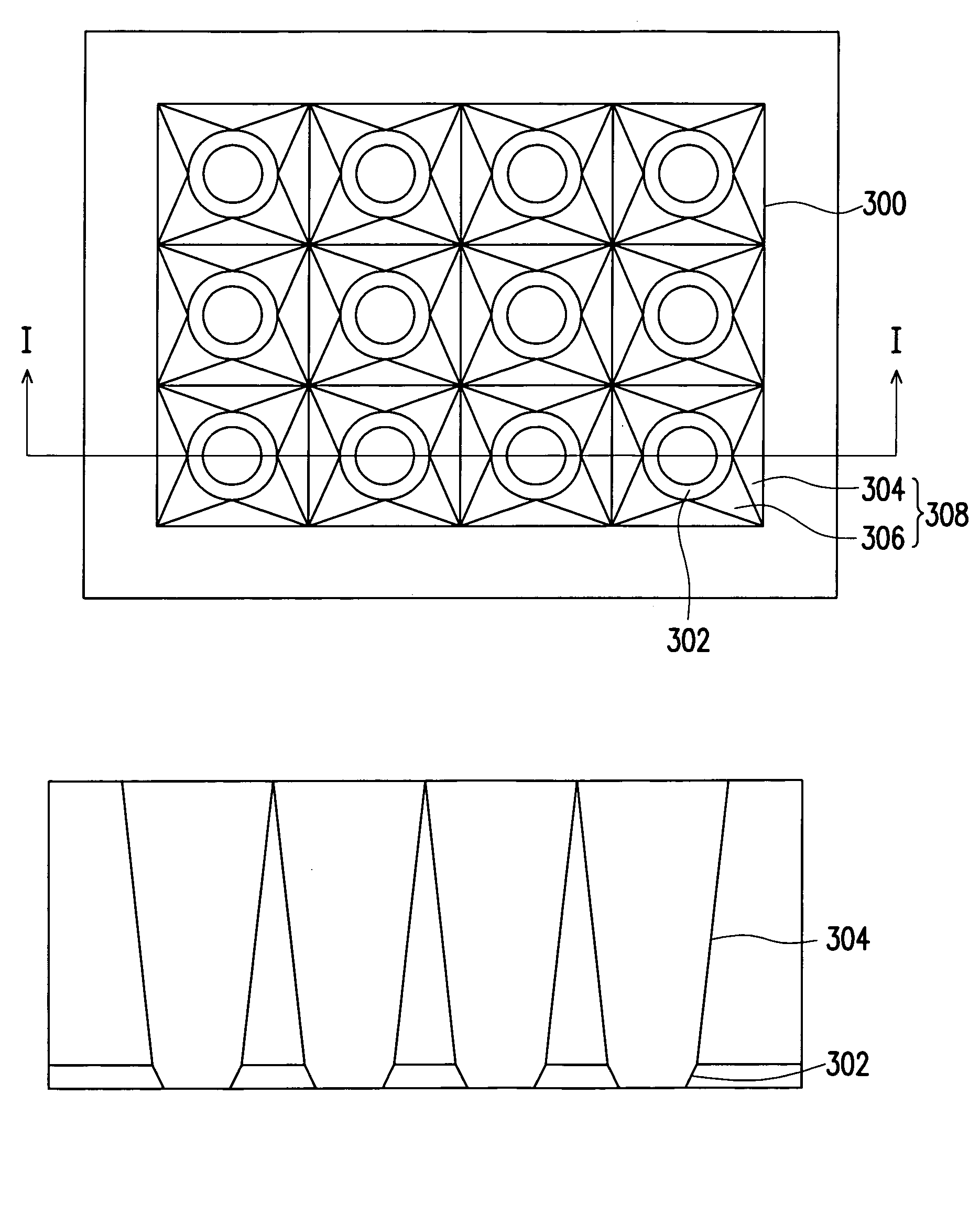
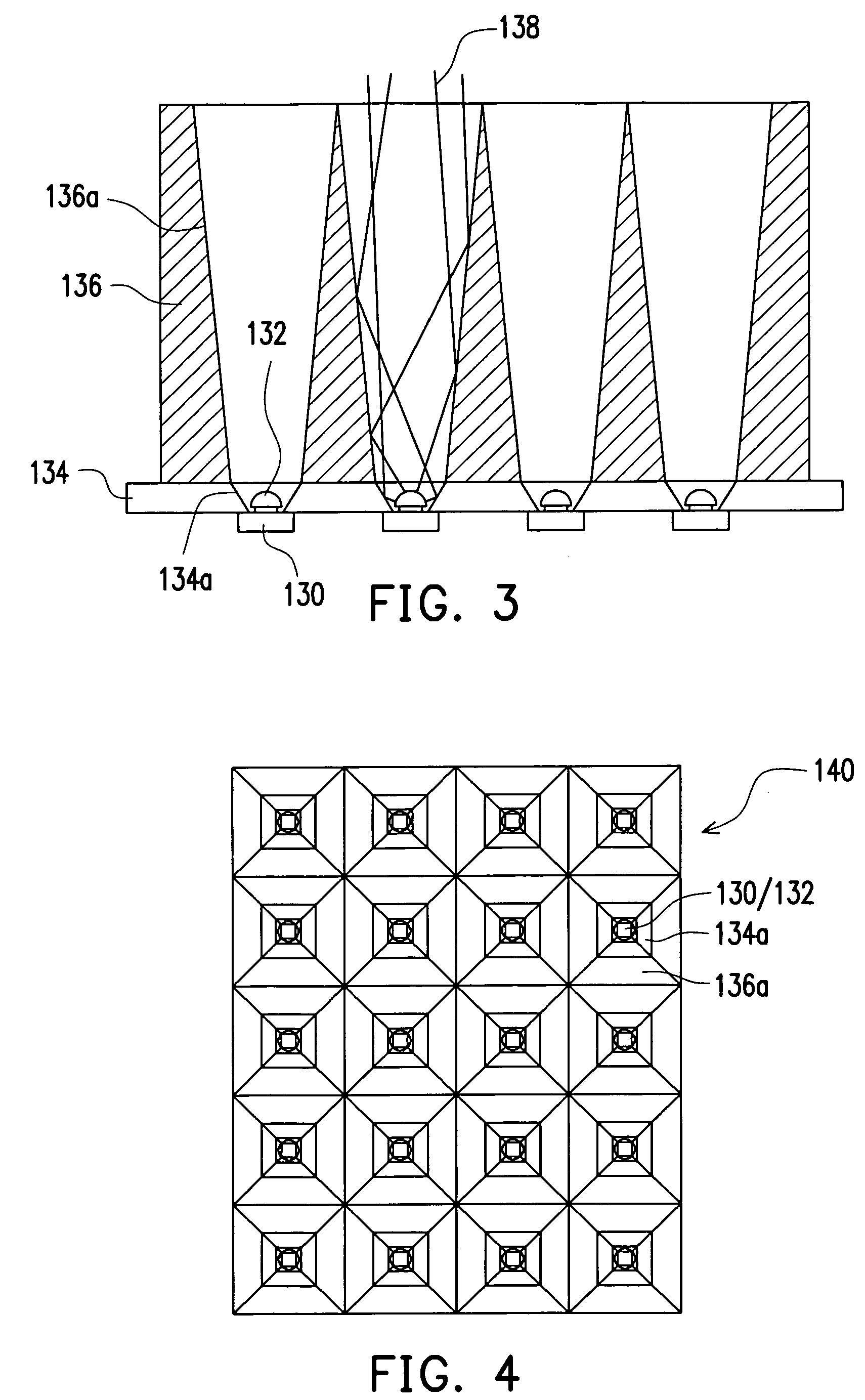
[0031]In general consideration on the issues for the conventional illuminating light source, the present invention proposes a novel design, so as to increase the illumination quality. The illumination light source of the present invention is formed from multiple illuminating units, which are arranged in an array. The illuminating units can be densely connected together to form the intended light-emitting plane. However, the light-emitting device of the illuminating unit is put together without being closely adjacent, so that it can effectively avoid excessively-high temperature, and therefore affecting the light-emitting efficiency. Some embodiments are provided for describing the features of the present invention, but the present invention is not just limited to the embodiment.

[0032]FIG. 3 is a cross-sectional view, schematically illustrating a structure of an illuminating light source, according to an embodiment of the present invention. FIG. 4 is a top view, schematically illustr...


PUM


Abstract

A structure of illuminating unit includes a point-like light-emitting device, having an optical axis. An initial-stage conoid-like reflective surface has a convergent opening end and a divergent opening end. The point-like light-emitting device is located at the convergent opening end and the optical axis is toward the divergent end for emitting light. The initial-stage conoid-like reflective surface and the optical axis include an initial-stage included angle. A final-stage conoid-like reflective surface has a convergent opening end and a divergent opening end. The convergent opening end of the final-stage conoid-like reflective surface is coupled with the divergent opening end of the initial-stage conoid-like reflective surface. The final-stage conoid-like reflective surface and the optical axis include a final-stage included angle. The initial-stage included angle is larger than the final-stage included angle.

Description

CROSS-REFERENCE TO RELATED APPLICATION[0001]This application claims the priority benefit of Taiwan application serial no.94125065, filed on Jul. 25, 2005.BACKGROUND OF THE INVENTION[0002]1. Field of Invention[0003]The present invention relates to an illuminating technology. More particularly, the present invention relates to a structure of an illuminating unit and a structure of an illuminating light source.[0004]2. Description of Related Art[0005]The artificial light source is a product always widely needed in our daily life, and, for example, is used to illuminate an object or an environment without the sun light, and further the image can be projected onto a screen for viewing by people and so on. As the development of scientific technology, the illuminating technology has been accordingly developed.[0006]For example, the light source applied in a projector is provided by a high-illumination light lamp, such as UHP, through a short arc by electric discharge. Then, the radiant lig...

Claims


Application Information

Patent Timeline
Patent Type & Authority Patents(United States)
IPC IPC(8): F21V7/00
CPCF21V7/09F21Y2101/02Y10S362/80G03B21/2033G03B21/208G03B21/2013F21Y2115/10
Inventor HAN, WEI-KUOTAIN, RA-MINCHEN, CHIN-LUNGLIAU, SHYI-CHING
Owner WALSIN LIHWA
Learn More