
Method and apparatus for variable bit-rate control in video encoding systems and computer program product therefor

a video encoding and variable bit-rate technology, applied in the field of video encoding, can solve the problems of bit-rate control being a central problem, cbr coding mode cannot guarantee a constant video quality for all scenes, and vbr coding mode cannot guarantee a constant output bit-rate for all scenes

Active Publication Date: 2008-03-25
STMICROELECTRONICS SRL
View PDF7 Cites 14 Cited by
  • Summary
  • Abstract
  • Description
  • Claims
  • Application Information

AI Technical Summary

Benefits of technology

[0097]An embodiment of the invention provides an improved solution for variable bit-rate control in

Problems solved by technology

Bit-rate control is a central problem in moving picture encoding systems.
Hence, a CBR coding mode cannot guarantee a constant video quality for all the scenes.
Therefore, a VBR coding mode cannot guarantee a constant output bit-rate for all the scenes.
Unfortunately, these objectives are conflicting in any CBR method: if too many bits are spent for past pictures, the control system must reduce the number of bits for the next pictures and these will have then a lower quality.
However, quantization noise is much more visible in uniform (low activity) areas, hence it is necessary to less coarsely quantize these ones.
A problem with this algorithm is the ideal uniform distribution of target bits over macro-blocks.
Another drawback of the TM5 algorithm is a poor behavior in case of scene changes.
This could be a problem for I-frames because the last I-picture may be more than ten images earlier (our GOP is composed of a number of frames at least greater than 12).
i) non-uniform distortion within a sequence (and even within a picture) gives rise to an output with non-uniform visual quality;
ii) bit allocation methods are inefficient, especially for sequence containing scenes of varying complexity; and
iii) poor performance at scene changes.
Also, the methods of WO-A-99 / 38333 and WO-A-99 / 49664 employ rate-distortion curves and therefore are exposed to the same problems.
The VBR method reported in U.S. Pat. No. 5,650,860 is a non-real time multi-pass encoder: the same GOP is encoded several times with different strategies to gather information about the way bits can be used in the final effective encoding; basically this represents a very sophisticated and expensive pre-analysis, to be used only on professional high-end equipments.
Both the methods of the work of Mohsenian et al. and WO-A-99 / 38333 are very complex: the first due to its PSNR computation, the second due to the minimization of a Lagrangian cost function (through Lagrange multipliers method).
A number of problems related to CBR and VBR methods have been already indicated in the foregoing.
This behavior also negatively affects the QPi variance and average values that are both higher than those for TM5.
The results obtained by using such curves is sub-optimal and requires accurate modeling that is very expensive in terms of computation.
The best option would certainly be to re-compute these curves several times at any frame, as done in the work of Ding et al., but this is prohibitive in terms of (extremely high) CPU computation, (longer) processing delay, (larger) memory capacity, for products targeting consumer application markets.
Therefore they inherently suffer—although partially—from the same limitations of TM5.

Method used


Image

  • Method and apparatus for variable bit-rate control in video encoding systems and computer program product therefor
  • Method and apparatus for variable bit-rate control in video encoding systems and computer program product therefor
  • Method and apparatus for variable bit-rate control in video encoding systems and computer program product therefor

Examples


Embodiment Construction

[0105]Embodiments of a method and apparatus for variable bit-rate control in video encoding systems and computer program product therefor are described herein. In the following description, numerous specific details are given to provide a thorough understanding of embodiments of the invention. One skilled in the relevant art will recognize, however, that the invention can be practiced without one or more of the specific details, or with other methods, components, materials, etc. In other instances, well-known structures, materials, or operations are not shown or described in detail to avoid obscuring aspects of the invention.

[0106]Reference throughout this specification to “one embodiment” or “an embodiment” means that a particular feature, structure, or characteristic described in connection with the embodiment is included in at least one embodiment of the present invention. Thus, the appearances of the phrases “in one embodiment” or “in an embodiment” in various places throughout ...


PUM


Abstract

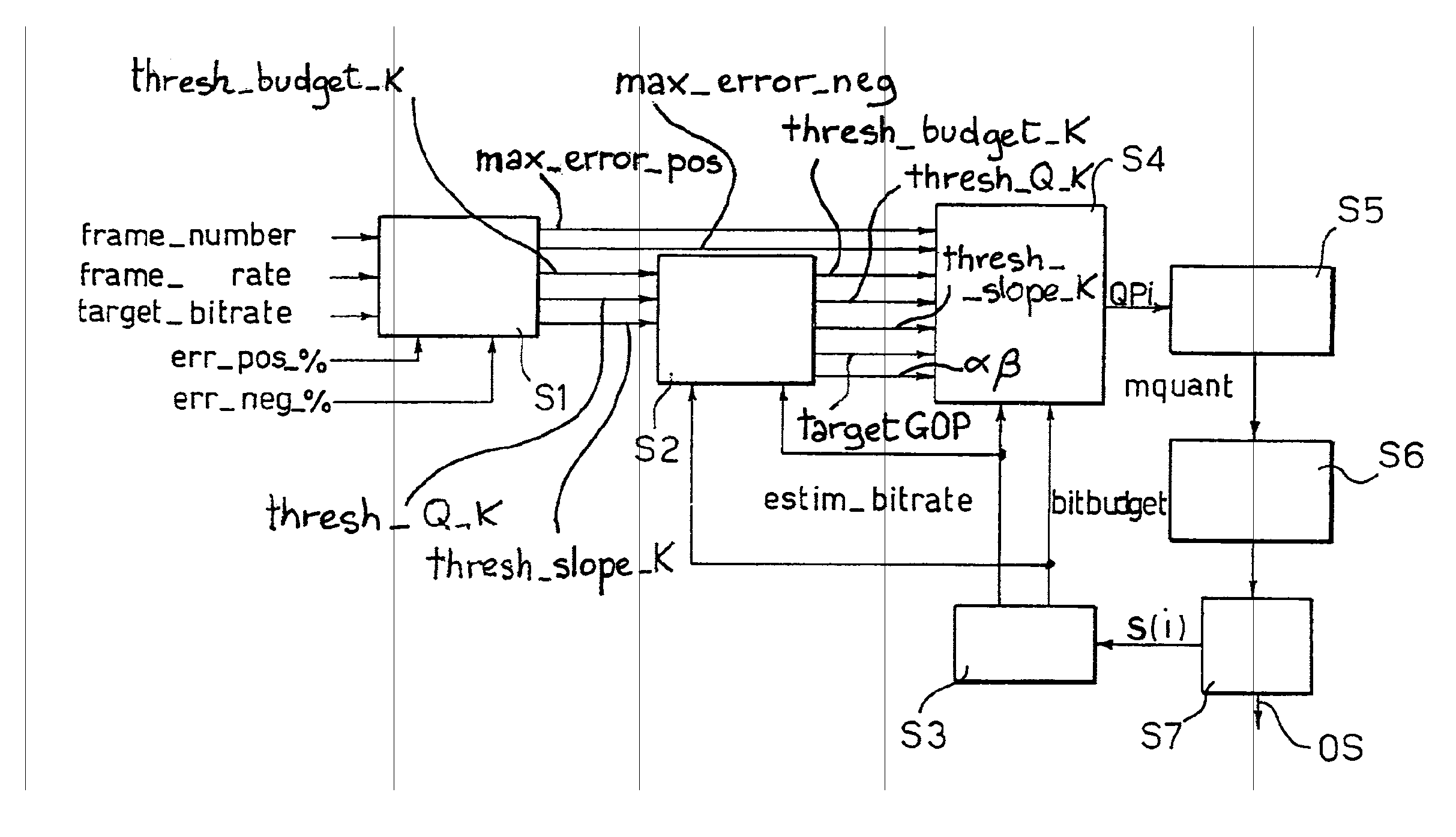
A method for controlling the bit-rate of a bitstream of encoded video signals at a variable bitrate, the bitstream being generated by compressing a video sequence of moving pictures, wherein each picture comprises a plurality of macroblocks of pixels compressed by any of transform coding, temporal prediction, bi-dimensional motion compensated interpolation or combinations thereof, to produce any of I and / or P and / or B frames, the method involving quantization of said macroblocks effected as a function of a quantization parameter. The method includes defining a target bit-rate as well as maximum positive and negative error values between the target bit-rate and an average value of the current bit-rate of the bitstream, controlling the current bit-rate in order to constrain it between said maximum positive and negative error values, and defining an allowed range of variation for updating at least one reference parameter representative of the average value of the quantization parameter over each picture, wherein said allowed range is determined as a function of the target bit-rate and the maximum positive and negative error values.

Description

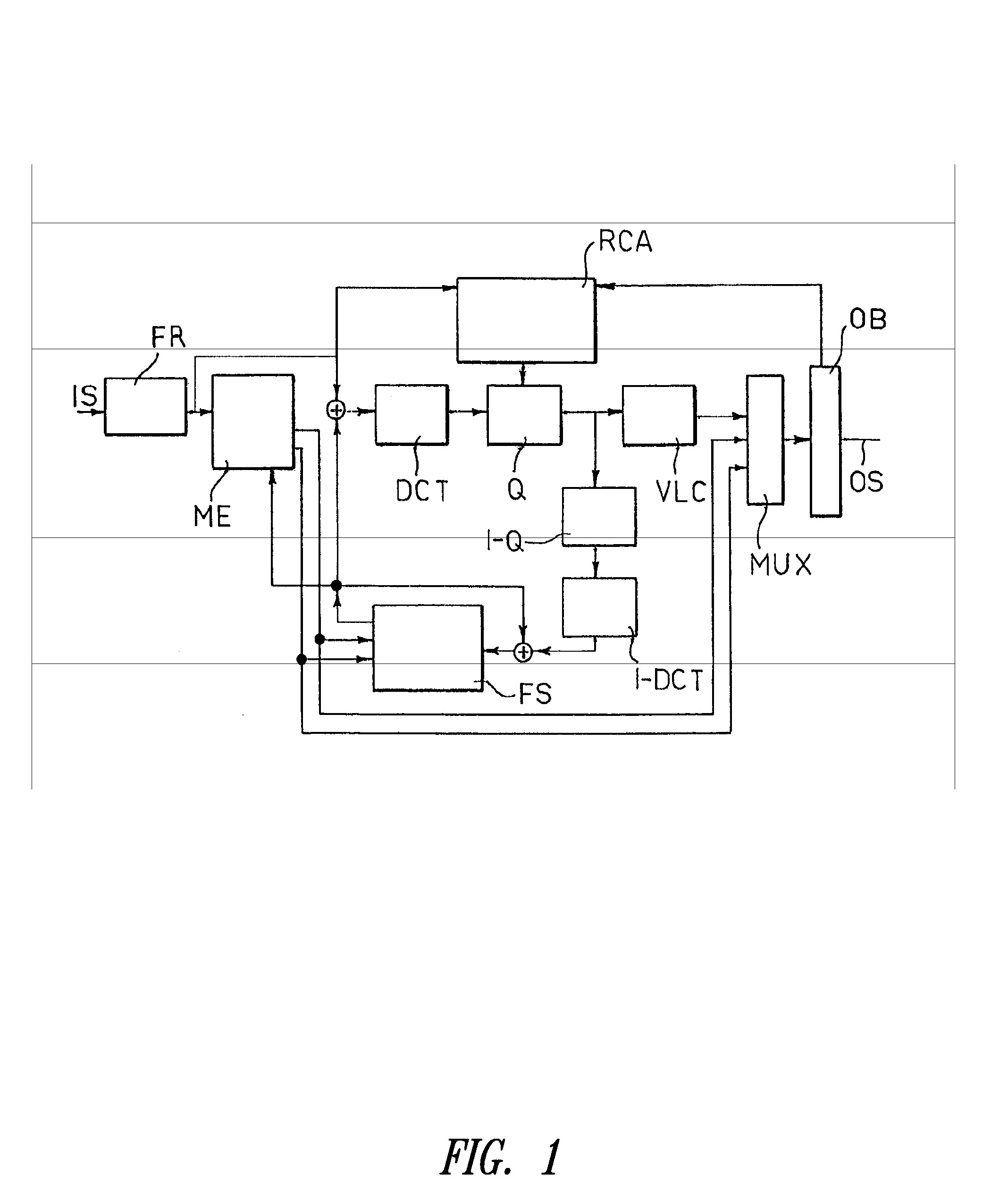
BACKGROUND OF THE INVENTION[0001]1. Field of the Invention[0002]The present disclosure relates to encoding of video signals.[0003]A number of video coding systems such as MPEG-2 (see, e.g., (MPEG-2) ISO / IEC 13818-2, Draft International Standard, 1995(E)), H.263 (see, e.g., DRAFT ITU-T Recommendation H.263, 1995), MPEG-4 (see, e.g., (MPEG-4) ISO / IEC 14496-2, Final Draft of International Standard, December 1998), H.26L (see, e.g., ITU-T VCEG Draft H.26L—Test Model Long-term number 8 (TML-8)) are based on a video compression procedure that exploits the high degree of spatial and temporal correlation in natural video sequences. In order to do this, video encoders decompose video sequences in Groups Of Pictures (briefly GOP) by differentiating the features of every picture, within the GOP, in two different classes: Intra and Inter coded images (or frames). Intra frames can be compressed without extra information, whereas Inter frames need either Inter or Intra frame to start their compre...

Claims


Application Information

Patent Timeline
IPC IPC(8): H04N7/12G06T9/00
CPCG06T9/005G06T9/007H04N19/159H04N19/172H04N19/152H04N19/15H04N19/61H04N19/124H04N19/149
Inventor BAGNI, DANIELEBENUSSI, FLAVIOBIFFI, BRUNO
Owner STMICROELECTRONICS SRL
Learn More