Cartridge loading devices

a technology of loading device and cassette, which is applied in the field of cassette loading device, can solve the problems of legacy tape cartridges not being usable, device and/or cartridge damage, and the limit of the storage capacity of a given size of cassettes

Active Publication Date: 2008-03-25
HEWLETT-PACKARD ENTERPRISE DEV LP
View PDF6 Cites 2 Cited by
  • Summary
  • Abstract
  • Description
  • Claims
  • Application Information

AI Technical Summary

Benefits of technology

[0014]The invention provides a cartridge loading device for magnetic tapes comprising housing means defining a housing for magnetic tape cartridges that can expand from a first size to a second size, guide means for controlling expansion of said housing from said first size to said second size and comprising at least one means defining a line of movement having a first end associated with said first size of said housing and a second end associated with said second size of housing, and a rotatable locking means for locking said housing means in a locked condition in which said housing is said first size, said first size having a first height and said second size having a second height, said second height being greater than said first height, said sizes of said housing being selected such that when said housing is said first size, it can receive first sized magnetic tape cartridges having a predetermined height and when said housing is said second size, it can receive second sized magnetic tape cartridges having a predetermined height that is greater than the height of said first sized magnetic tape cartridges, and said locking means being actuable by insertion of a second sized cartridge into said housing to release said housing means from said locked condition to permit expansion of said housing from said first size to said second size and having an axis of rotation located on a line that is in line with at least a first portion of a line of movement defined by said at least one means defining a line of movement, which first portion extends from said first end of the line of movement.

Problems solved by technology

However, ultimately, the storage capacity of a given size of tape has a limit.
This then provides the user with the problem that legacy format tape cartridges would not be usable with the new tape drive and so it would be necessary to maintain more than one tape drive or transfer existing stored data to the wider tape.
The result is that an incorrectly oriented cartridge can only be inserted by using an unnaturally large force, usually such as would result in damage to the device and / or cartridge.
However, the conventional means rely on the rigidity of the cartridge loading device.
In an expandable cartridge loading device as proposed by the applicant, this is more problematical, since there will be parts that move relative to each other in order to provide the expansion and this makes it more difficult to manufacture to tight tolerances.

Method used


Image

  • Cartridge loading devices
  • Cartridge loading devices
  • Cartridge loading devices

Examples


Embodiment Construction

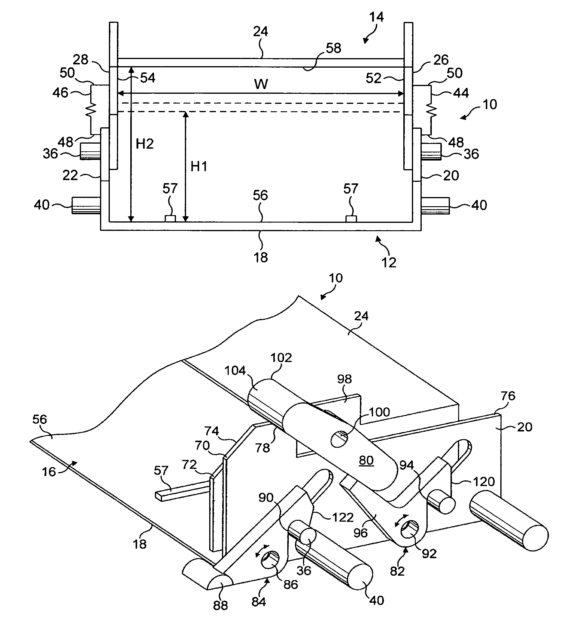
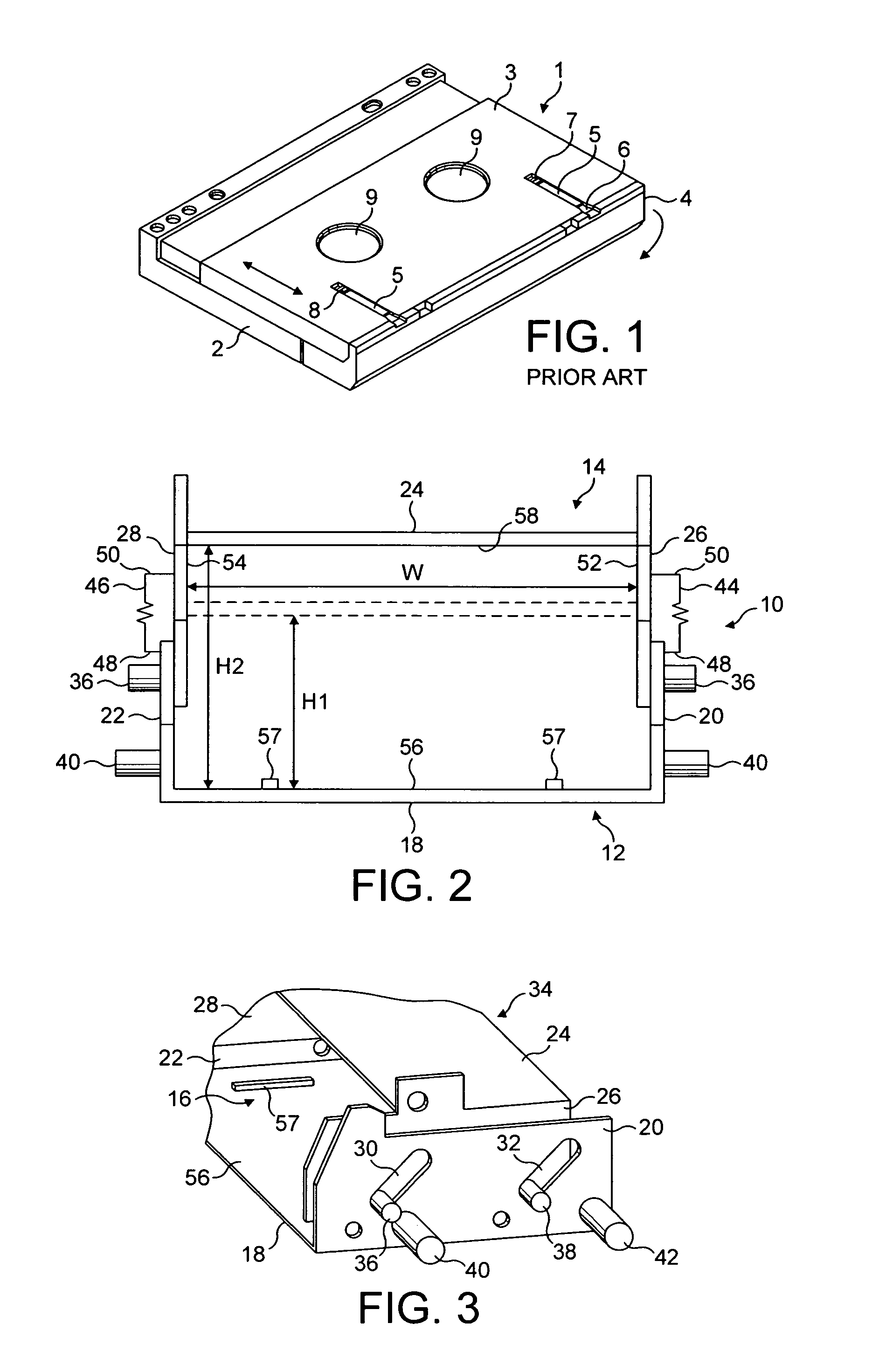
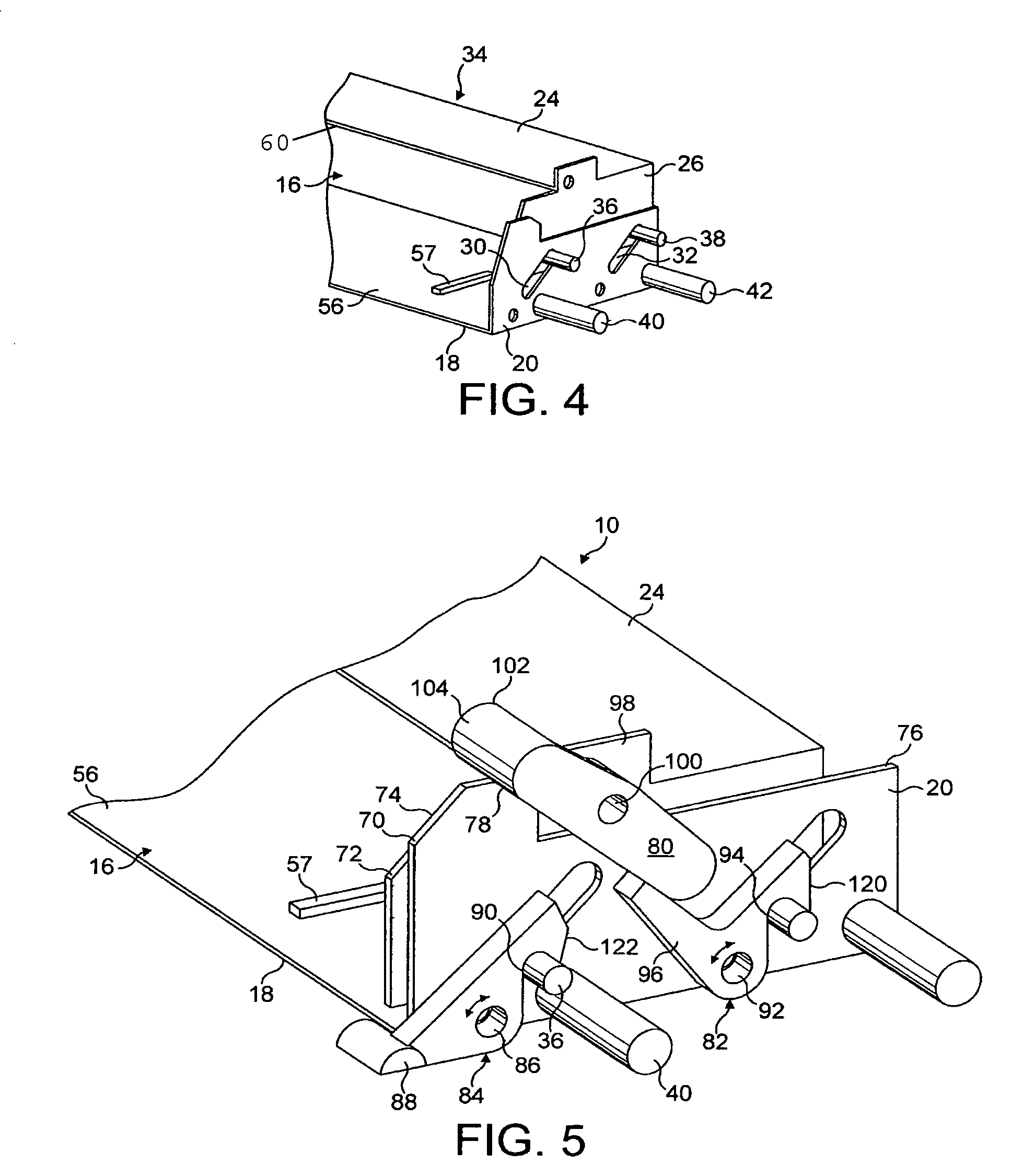
[0025]Referring to FIG. 2, a cartridge loading device 10 for magnetic tape cartridges used for storage of digital data comprises a first member 12 and a second member 14. Each member 12, 14 comprises a generally U-shaped channel and the two channels are oppositely disposed so as to define a housing for magnetic tape cartridges that has a substantially rectangular opening 16.

[0026]The U-shaped channel of the first member 12 comprises a horizontally disposed base or floor portion 18 and opposed upstanding limbs 20, 22 that extend perpendicular to the base portion 18. The U-shaped channel of the second member 14 comprises a horizontally disposed upper or roof portion 24 and opposed depending limbs 26, 28 that extend perpendicular to the roof portion and parallel to the limbs 20, 22 of the first member 12. The arrangement is such that the limbs 26, 28 of the second member are disposed inside of, and adjacent and parallel to, the respective limbs 20, 22 of the first member 12.

[0027]The l...


PUM

PropertyMeasurementUnit
widthaaaaaaaaaa
depthaaaaaaaaaa
depthaaaaaaaaaa

Abstract

A cartridge loading device 10 for magnetic tape cartridges includes a first member 12, a second member 14 movable relative to the first member from a first position to a second position and a guide arrangement for guiding movement of the second member between its first and second positions. The guide arrangement includes a projection 38 received in an elongate guide track 32 defining a line of movement having a first end that defines the first position of the second member 14 and a second end that defines its second position. The cartridge loading device also has a locking system that includes a pivotable locking member 82 engageable with the projection 38 for locking the second member in its first position. The cartridge loading device can receive two different sizes of cartridge that correspond to the two positions of the second member. The locking member is actuable by insertion of a cartridge having the larger of two sizes into the device to release the projection to permit movement of the second member from the first position to the second position. The pivotable locking member 82 has a pivot point 92 disposed on a line that is in line with at least a first portion of the line of movement. The first portion extends from the first end of the line of movement.

Description

FIELD OF THE INVENTION[0001]The invention relates to cartridge loading devices for magnetic tape cartridges used for storage of digital data.BACKGROUND TO THE INVENTION[0002]Magnetic tape is commonly used for storage of digital data. The magnetic tape is spooled on reels in a cartridge that is insertable into a digital data transfer apparatus in which data can be written onto the tape and / or data can be read from the tape. Such data transfer apparatus, which may be referred to as a tape drives, typically includes a tape head for one or both of reading and / or writing data from or to the tape head.[0003]Known tape drives are generally designed to use a predetermined size tape cartridge that contains tape having a known width. Known cartridge loading devices of tape drives are generally designed to be used with a particular size of cartridge. Such devices conventionally include means for ensuring that only cartridges of the correct size can be inserted and then only when the cartridge ...

Claims


Application Information

Patent Timeline
Patent Type & Authority Patents(United States)
IPC IPC(8): G11B5/008G11B15/00G11B15/675G11B25/06G11B33/12
CPCG11B15/67555G11B25/066G11B33/121
Inventor TURNER, PHILIPDILLON, MARKFERNIHOUGH, ANDREW MARK
Owner HEWLETT-PACKARD ENTERPRISE DEV LP
Why Eureka
Try Eureka