
Method and apparatus for variable tension cord recoil and tethered user interface

Active Publication Date: 2008-03-18
ROCKWELL COLLINS INC
View PDF4 Cites 18 Cited by
  • Summary
  • Abstract
  • Description
  • Claims
  • Application Information

AI Technical Summary

Benefits of technology

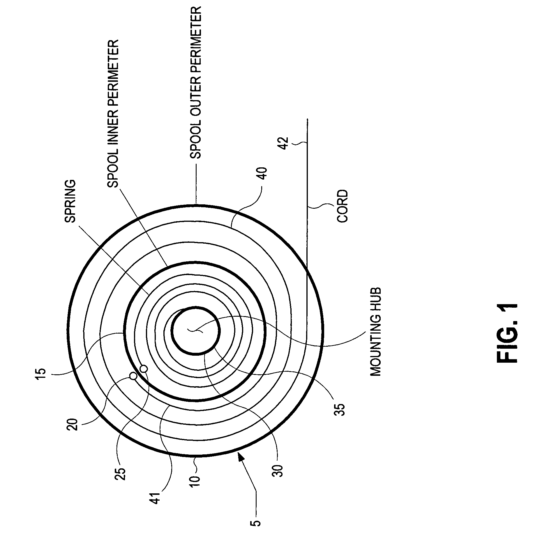
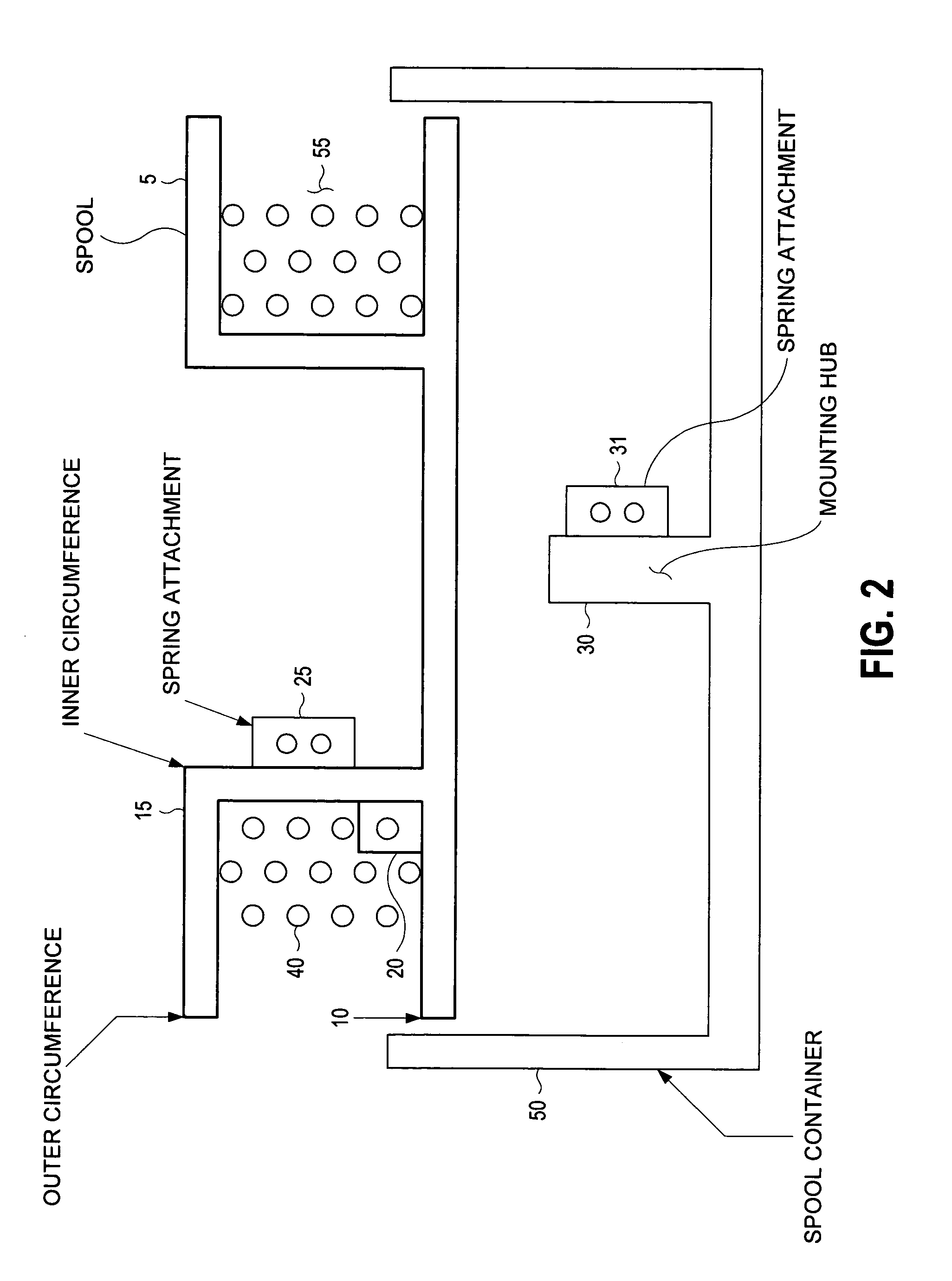
[0006]The present invention comprises a method for dispensing a cord from a spool using variable tension. By applying an increasing amount of pull tension as more cord is drawn from the spool, the cord is prevented from experiencing the sudden tensile stress associated with the end of the pull cycle. To enable this effect, the method of the present invention provides for mounting the spool onto a mounting hub. The mounting hub is typically part of a spool container that is used to mount a spool. According to one method of the present invention, the spool comprises an inner perimeter and a cord take-up channel. By providing a variable spring constant spring that is attached to and spirally wound about the mounting hub and then attached to the inner perimeter of the spool, the method provides for the application of variable tension to a cord that is drawn from the spool. Hence, as the cord is drawn from the spool, a weaker tension is applied to cord in order to allow a user to easily draw the cord from the spool. Toward the end of the pull cycle, the tension is increased in order to ensure that the rate at which the cord is drawn from the spool is reduced. This relieves the sudden impulse of tensile stress that the cord would otherwise experienced once it reaches the end of the pull cycle.

Problems solved by technology

Irrespective of the application, a cord that may be pulled from a spool is always susceptible to failure.
This tensile force induces a stress-oriented failure.
Where the cord is used for electrical connections, as in the user interface application described above, failure may be catastrophic.
In other applications, the failure may also be catastrophic, but the wear and tear experienced by the cord is generally visible before an actual failure occurs.
In the electrical connection case, failure of the electrical cord that is used to tether a user interface device may not be detectable by visual inspection.
These types of failures are exceptionally common where the application of the recoil mechanism constitutes use by members of the public.
Each time a passenger draws the user interface device from the cradle, the electrical cord used to effect a connection to the IFE system is fatigued at the end of the pull cycle; leading to eventual and inevitable failure.

Method used


Image

  • Method and apparatus for variable tension cord recoil and tethered user interface
  • Method and apparatus for variable tension cord recoil and tethered user interface
  • Method and apparatus for variable tension cord recoil and tethered user interface

Examples


Embodiment Construction

[0022]FIG. 1 is a pictorial representation of a recoil mechanism that applies variable tension to a cord according to the present invention. According to one illustrative embodiment of the present invention, a recoil mechanism may comprise a containment spool 5 that is mounted onto a hub 30. The containment spool typically has an outer perimeter or circumference 10 and an inner perimeter or circumference 15. The inner perimeter 15 of the containment spool typically has an inner surface and an outer surface relative to the center of the spool.

[0023]According to this example embodiment, a cord 40 is wrapped spirally about the inner perimeter 15 comprising the containment spool 5. The cord 40 may be attached to an attachment point comprising the containment spool 5. The attachment point 20 is typically disposed proximate to the inner perimeter 15 of the containment spool 5. For the sake of clarity, the cord 40 may have a first end 41 that is typically attached to the attachment point c...


PUM


Abstract

Variable tension is applied to a cord as it is drawn from a spool. More tension is applied to the cord as more cord is drawn preventing impulse stress. Cord used to attach user interface device for receiving input and presenting information.

Description

FIELD OF THE INVENTION[0001]This invention relates generally to cord recoil mechanisms and tethered user interfaces.BACKGROUND OF THE INVENTION[0002]Various apparatus have long used a tension-based recoil system that enables a tether or pull cord to be drawn back onto a spool. One of the most common examples of such a device is that of small motor that comprises a “pull-start”. A cord is typically wound concentrically about a containment spool. One end of the cord is typically attached proximate to the inner circumference of the containment spool. When the cord is drawn out off of the spool by pulling its free end, the containment spool rotates. This results in rotational work that may then be conveyed to the crankshaft of a small motor by a one-way clutch mechanism. Once the cord has been drawn to the completion of its cycle, a recoil means that is attached to the containment spool cause the spool to rotate in an opposite direction. This causes the cord to be taken back up onto the...

Claims


Application Information

Patent Timeline
IPC IPC(8): B65H75/48
CPCB65H75/486
Inventor ROYER, JOEL D.BARBA, RENE L.WOLFE, DOUGLAS J.OLAUSON, STEVE C.
Owner ROCKWELL COLLINS INC
Learn More