Regulator insert with hydraulic damping in outlet

a technology of hydraulic damping and valve insert, which is applied in the direction of space heating and ventilation details, heating types, domestic heating details, etc., can solve the problem of inability to complete the closure of the valve by means of a roller membrane, and achieve the effect of slowing down the reaction

Inactive Publication Date: 2008-03-18
FLOWCON INT
View PDF9 Cites 3 Cited by
  • Summary
  • Abstract
  • Description
  • Claims
  • Application Information

AI Technical Summary

Benefits of technology

[0009]According to a preferred embodiment the insert is provided with a central pipe which is in connection with a space above the roller membrane, which central pipe is throttled by an element which exhibits only a very small opening. When such regulator insert is used in a heating plant, the central pipe is connected to the flowing liquid, and the closure of the outflow openings is thus determined by the pressure conditions prevailing at any time across and through the insert and the pressure measured from the outside via the central pipe. The size of the opening in the element throttling the central pipe defines the response time of the system: the smaller the opening, the slower the reaction.

Problems solved by technology

This is accomplished by configuring the regulator insert to have slot-shaped outflow openings which have at least two different lengths, whereby complete closure of at least some of the outflow openings can take place only consecutively, and at least one of the slot-shaned outflow openings has such length that complete closure thereof by means of a roller membrane is not possible.
By moreover configuring the regulator insert such that complete closure of the outflow openings is not possible, it is accomplished that the insert never reaches this extreme position.

Method used


Image

  • Regulator insert with hydraulic damping in outlet
  • Regulator insert with hydraulic damping in outlet

Examples


Embodiment Construction

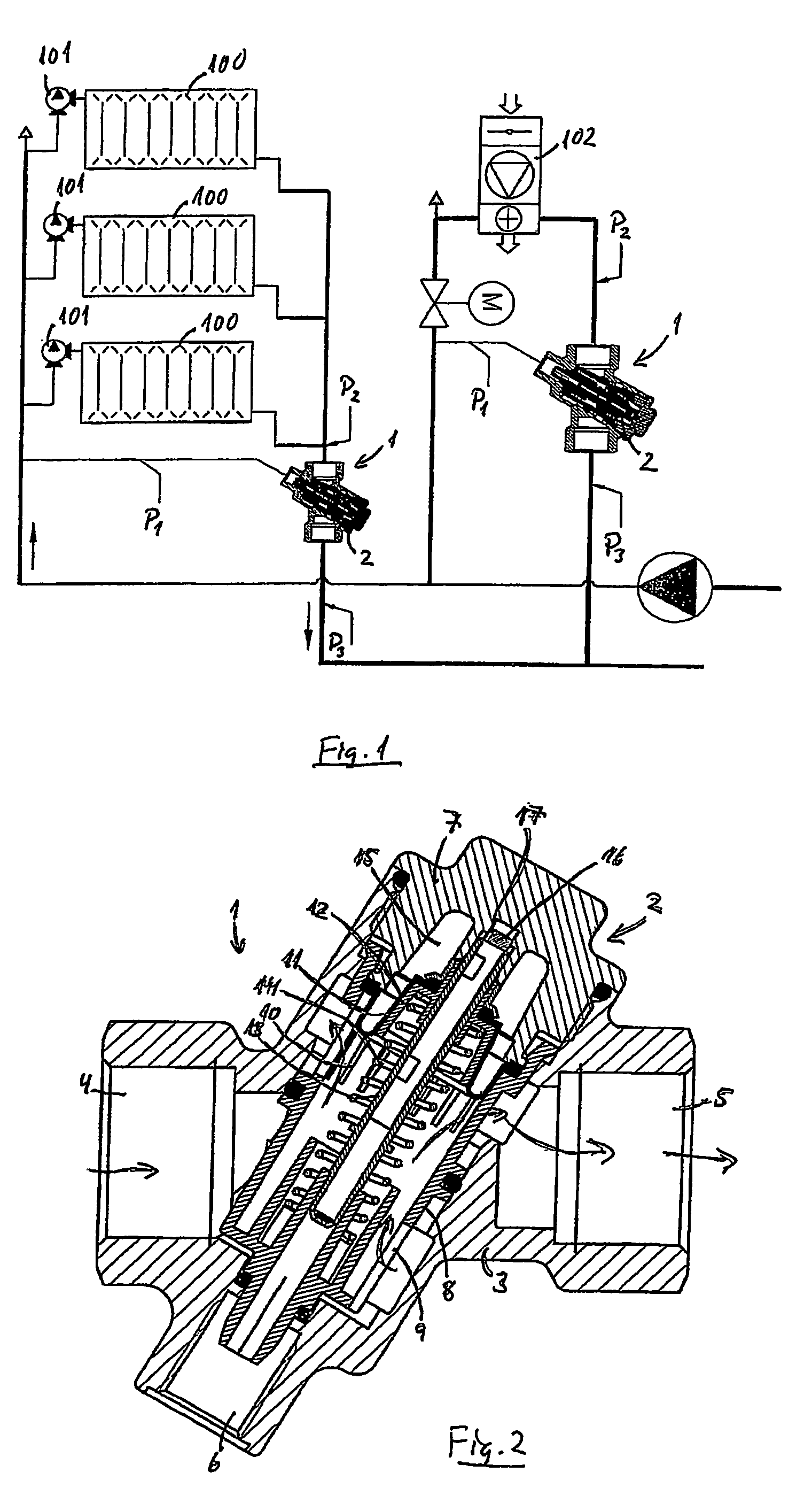
[0014]FIG. 1 schematically shows a sectional view of a heating plant, which uses regulator valves 1 with inserts 2 according to the invention for regulating a constant differential pressure (P1−P2) across the individual distribution strings. FIG. 1 is a sectional view showing two distribution strings, wherein the heat-carrying medium is distributed to three respective radiators 100 with thermostatic regulator valves 101 and to an air-heating terminal 102 regulating the injected air to a given temperature via a thermostatic regulator valve and heat exchange between the heat-carrying medium and a forced flow of air.

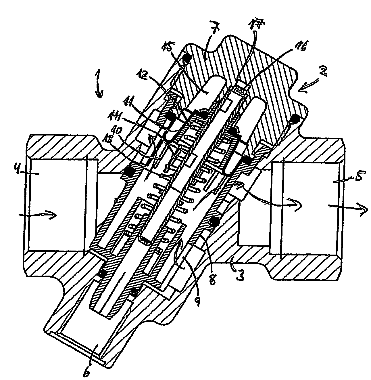
[0015]Each regulator valve 1 is arranged on the return string with a capillary-tube connection to the lead string. A given differential pressure across the distribution string between the connection point on the lead string and the inlet of the regulator valve 1 is maintained to a magnitude determined by the interaction between a spring 14 and a roller membrane 11 (see belo...


PUM


Abstract

A regulator insert for valves includes inflow openings and a plurality of slot-shaped outflow openings extending in the axial direction of the insert and being, via a roller membrane, closable in response to the difference in pressure across the insert under the influence of a spring that seeks to keep the outflow openings open. The slot-shaped outflow openings have at least two different lengths, whereby complete closure of at least some of the outflow openings can take place only consecutively. At least one of the slot shaped outflow openings has such length that complete closure thereof by means of the roller membrane is not possible.

Description

BACKGROUND OF THE INVENTION[0001]1. Field of the Invention[0002]The invention relates to a regulator insert for valves, such as valves used for controlling liquid flow in a plant for central heating or air conditioning.[0003]2. The Prior Art[0004]Such regulator insert is known from eg WO 95 / 12082 showing a regulator insert that comprises a housing which is, at the one end, provided with radial inflow openings and, at the one end, provided with radial inflow openings and, at the other end, with radial and axially extending slot-shaped outflow openings. The insert is configured with a roller membrane that closes off the outflow openings to a smaller or larger degree in response to the difference in pressure across the insert, so as to accomplish an essentially constant liquid flow through the insert. The roller membrane is influenced by two oppositely oriented forces; viz, on the side where the outflow openings are located, by the pressure within the insert and a helical spring that s...

Claims


Application Information

Patent Timeline
Patent Type & Authority Patents(United States)
IPC IPC(8): F16K3/26F24D19/10
CPCF24D19/1015Y10S137/901G05D16/0608G05D16/028Y10T137/7805Y10T137/86734
Inventor MOESBY, PETER
Owner FLOWCON INT
Why Eureka
Try Eureka