
Goggles structure

a technology of goggles and structures, applied in the field of goggles structure, can solve the problems of increasing the overall weight, burden of wearing, increasing the overall rigidity, etc., and achieve the effects of reducing the overall weight and rigidity of the pair of goggles, improving the comfort of wearing, and improving the softness

Active Publication Date: 2008-03-18
JIURU
View PDF7 Cites 49 Cited by
  • Summary
  • Abstract
  • Description
  • Claims
  • Application Information

AI Technical Summary

Benefits of technology

"The present invention provides a goggles structure that reduces the weight and rigidity of the frame, improving the comfort of wearing. It also provides better ventilation and a safety reminder structure to prevent misuse or damage. The goggles structure includes a goggles frame with a rigid frame and an elastic face connecting section, and a lens with hanging hooks for hanging and fixing the lens onto the frame. The head strap connecting means is used to secure the lens to the frame, preventing the lens from falling out. Overall, the goggles structure provides improved comfort, ventilation, and safety."

Problems solved by technology

Such frame not only increases the overall weight and causes a burden for wearing, but also increases the overall rigidity so that a better softness cannot be achieved.
2. The performance of the ventilation structure is not good enough, since it has to concurrently take the ventilation and the prevention of liquid spluttering into consideration, particularly when the airflow inside the goggles has several bended positions at the bottom of the internal side and the top of the goggles, and thus the moisture will be attached on the internal side of the lens easily which will affect the wearer's vision.
3. If the transparent lens of the prior art goggles is removed or the head strap is changed, the wearer may forget to reinstall the lens before wearing the goggles.
It is not easy for the wearer to find out at the beginning, and there exists a risk of getting injured.
Some of the prior art goggles come with a fixed lens, but the fixed lens may come out by accident if there is a strong external force, and it thus exist a potential risk.

Method used


Image

  • Goggles structure
  • Goggles structure
  • Goggles structure

Examples


Embodiment Construction

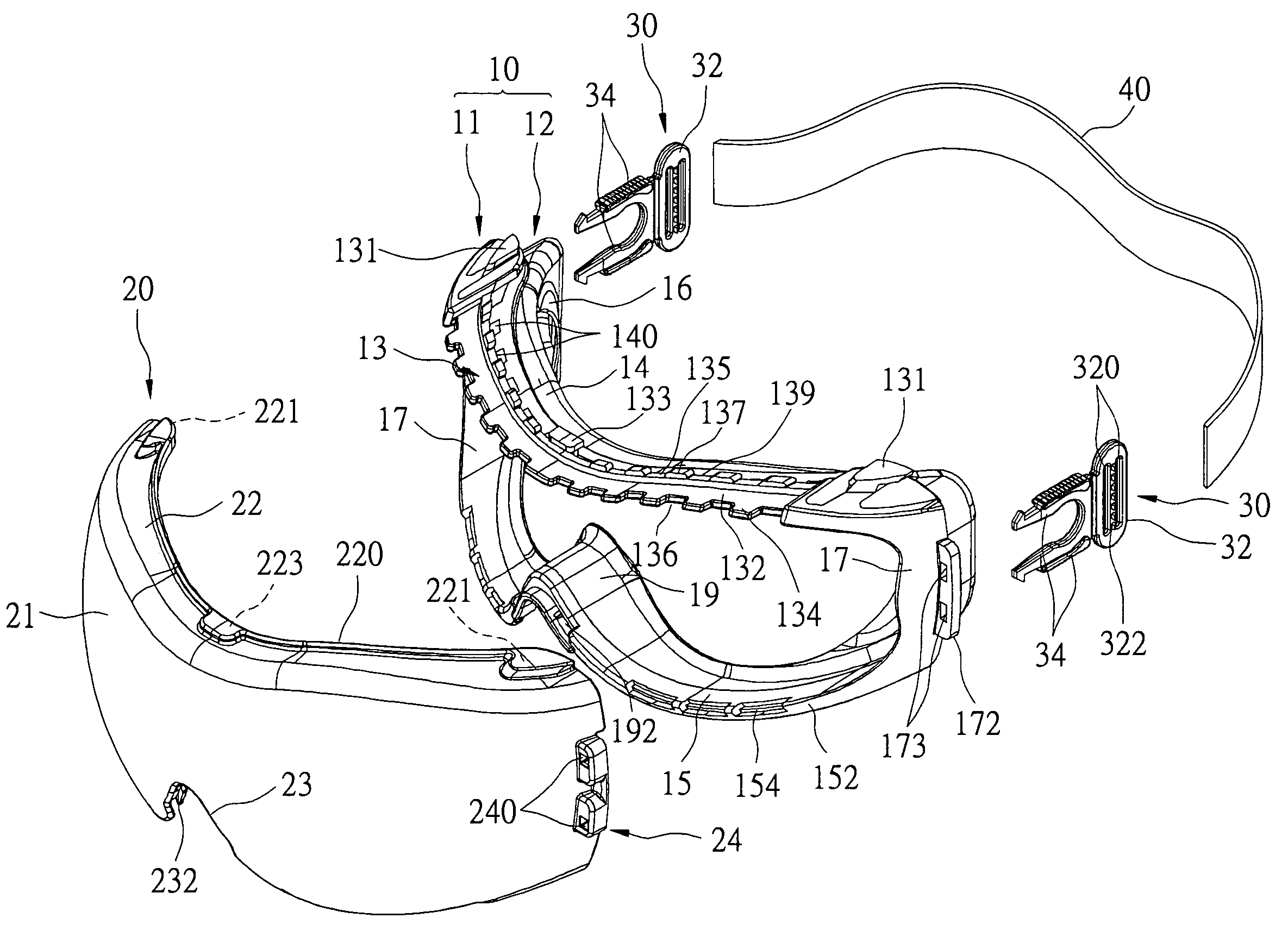
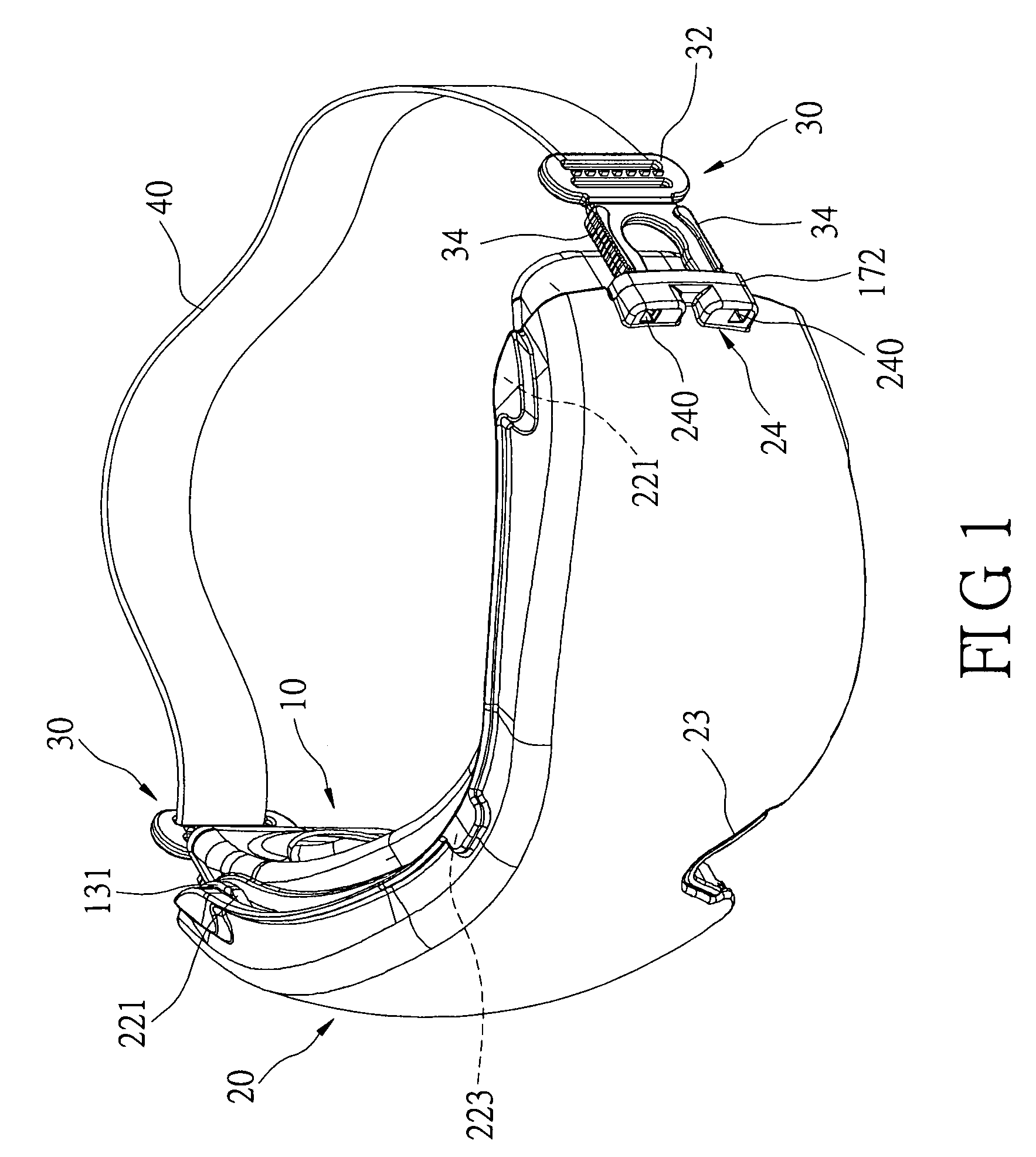
[0029]Refer to FIG. 1 for the perspective view of a goggles structure of the invention. The present invention provides a goggles structure comprising a goggles frame 10, a lens 20, a pair of head strap connecting means 30, and a head strap 40. The goggles are used for protecting a wearer's eyes, which is applicable for wearing while the wearer is doing exercises, and particularly applicable for preventing objects from hitting the wearer's eyes or liquids from spluttering into the eyes.

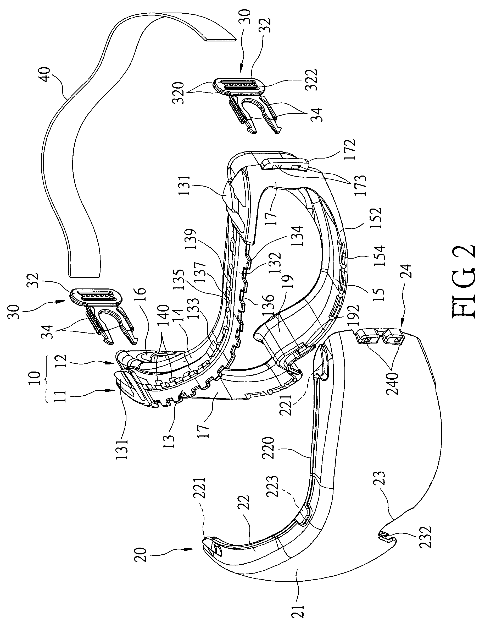
[0030]Refer to FIGS. 2 to 4 respectively for the exploded view, top view and bottom view of the of the goggles structure of the present invention. The goggles frame 10 includes a rigid frame 11 and an elastic face connecting section 12. The face connecting section 12 is connected to the internal side of the frame 11, and the face connecting section 12 and the frame 11 are generally coupled with each other by a plastic injection method. The frame 11 can provide appropriate structural strength for the go...


PUM


Abstract

A goggles structure reduces its overall weight and rigidity to improve the comfort of wearing, which provides better ventilation and prevents its wearing without a lens. The goggles comprise a goggles frame including a frame and a connecting section, a lens, a pair of head strap connecting means, and a head strap. At least one hanging hook is protruded from the top of the frame. A plurality of hanging holes corresponding to the hanging hooks is disposed at the top and bottom of the lens for fixing the lens onto the frame. The head strap latches the head strap connecting means onto both sides of the lens for preventing the lens from falling out accidentally. When the goggles are not used, the latching force disappears and allows its removal for cleaning. A ventilation structure disposed inside the lens is provided to prevent splattering.

Description

BACKGROUND OF THE INVENTION[0001]1. Field of the Invention[0002]The present invention relates to a goggles structure that protects a wearer's eyes and prevents foreign matters from entering into the eyes and resists small quantity of splattered liquid or melted metal according to the general safety protection rules.[0003]2. Description of Related Art[0004]Referring to U.S. Pat. No. 5,617,588 entitled “Snap together protective goggle construction with toric lens” and published on Apr. 8, 1997 for the prior art protective goggles, the objectives of the patent include:[0005]1. Fitting different sizes of faces;[0006]2. Avoiding spluttered or sprayed liquid;[0007]3. Producing airflow that can prevent mists formed on the lens; and[0008]4. Providing an adjustable head strap buckle.[0009]However, the aforementioned prior art still has the following shortcomings:[0010]1. The rigid frame disposed between the lens and the face connecting section must have sufficient structural strength to supp...

Claims


Application Information

Patent Timeline
Patent Type & Authority Patents(United States)
IPC IPC(8): A61F9/02
CPCA61F9/026G02C11/08
Inventor LIN, TITAN
Owner JIURU
Learn More