
Sound effecter, fundamental tone extraction method, and computer program

a sound effecter and fundamental tone technology, applied in the field of sound effecters, can solve the problem of poor frequency of fundamental tone in the first waveform rather than other frequencies

Active Publication Date: 2008-03-11
CASIO COMPUTER CO LTD
View PDF5 Cites 9 Cited by
  • Summary
  • Abstract
  • Description
  • Claims
  • Application Information

AI Technical Summary

Benefits of technology

[0009]A harmonic overtone has a frequency which is integer number times higher than that of a fundamental tone. Under this fact, the greatest common divisor among the frequencies corresponding to 2 or more frequency channels including frequency components of the harmonic overtone (harmonic channel) will be handled as information showing frequency of the fundamental tone. That is, such the greatest common divisor is helpful for generating the second waveform representing a target fundamental tone after exactly shifting the fundamental tone of the first waveform. This method avoids extracting (detecting) a fundamental tone of the first waveform. Therefore, it is able to generate the second waveform having the target fundamental tone, even if the fundamental tone in the first waveform is missed (so called, missing fundamental) or the frequency of the fundamental tone in the first waveform is very poor rather than other frequencies. On the otherwise, the greatest common divisor of the present invention is also helpful for exactly extracting (detecting) the frequency of the fundamental tone in the first waveform.

Problems solved by technology

Therefore, it is able to generate the second waveform having the target fundamental tone, even if the fundamental tone in the first waveform is missed (so called, missing fundamental) or the frequency of the fundamental tone in the first waveform is very poor rather than other frequencies.

Method used


Image

  • Sound effecter, fundamental tone extraction method, and computer program
  • Sound effecter, fundamental tone extraction method, and computer program
  • Sound effecter, fundamental tone extraction method, and computer program

Examples


Embodiment Construction

[0018]Embodiments of the present invention will now be described with reference to drawings.

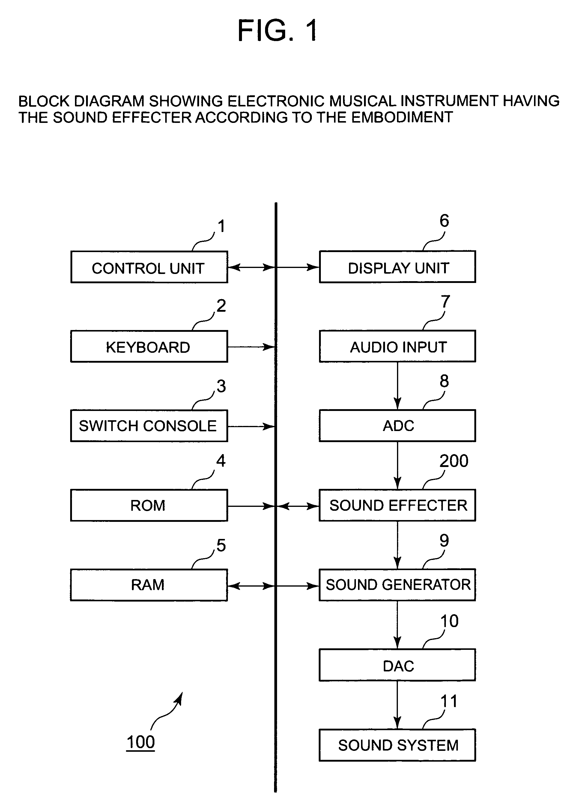
[0019]FIG. 1 is a block diagram exemplifying the structure of an electronic musical instrument 100 having a sound effecter 200 according to the present invention.

[0020]As shown in FIG. 1, the electronic musical instrument 100 comprises a control unit 1, a keyboard 2, a switch console 3, a ROM 4, a RAM 5, a display unit 6, an audio input 7, an ADC 8, a sound generator 9, a DAC 10, a sound system 11, and the sound effecter 200.

[0021]The control unit 1 may comprise a CPU (Central Processing Unit) for controlling whole of the instrument.

[0022]The keyboard 2 comprises piano like keys as a user interface for playing music.

[0023]The switch console 3 comprises various kinds of switches to be operated by a user for settings. In addition to such the user operable switches, the switch console 3 may have detector circuits for detecting states of the user operable switches.

[0024]The ROM 4 is a Read Only M...


PUM


Abstract

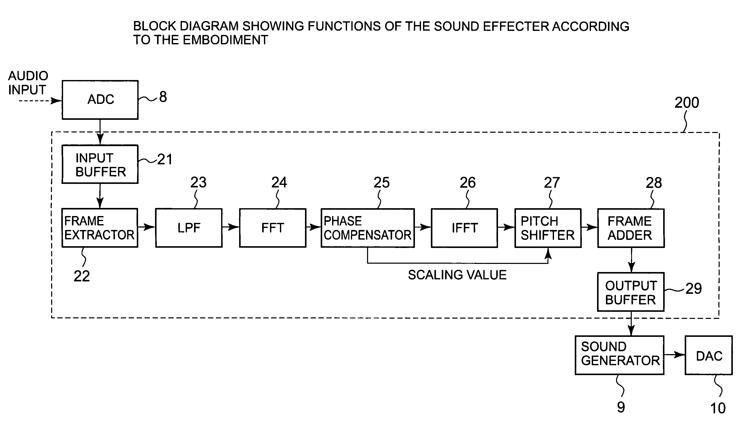
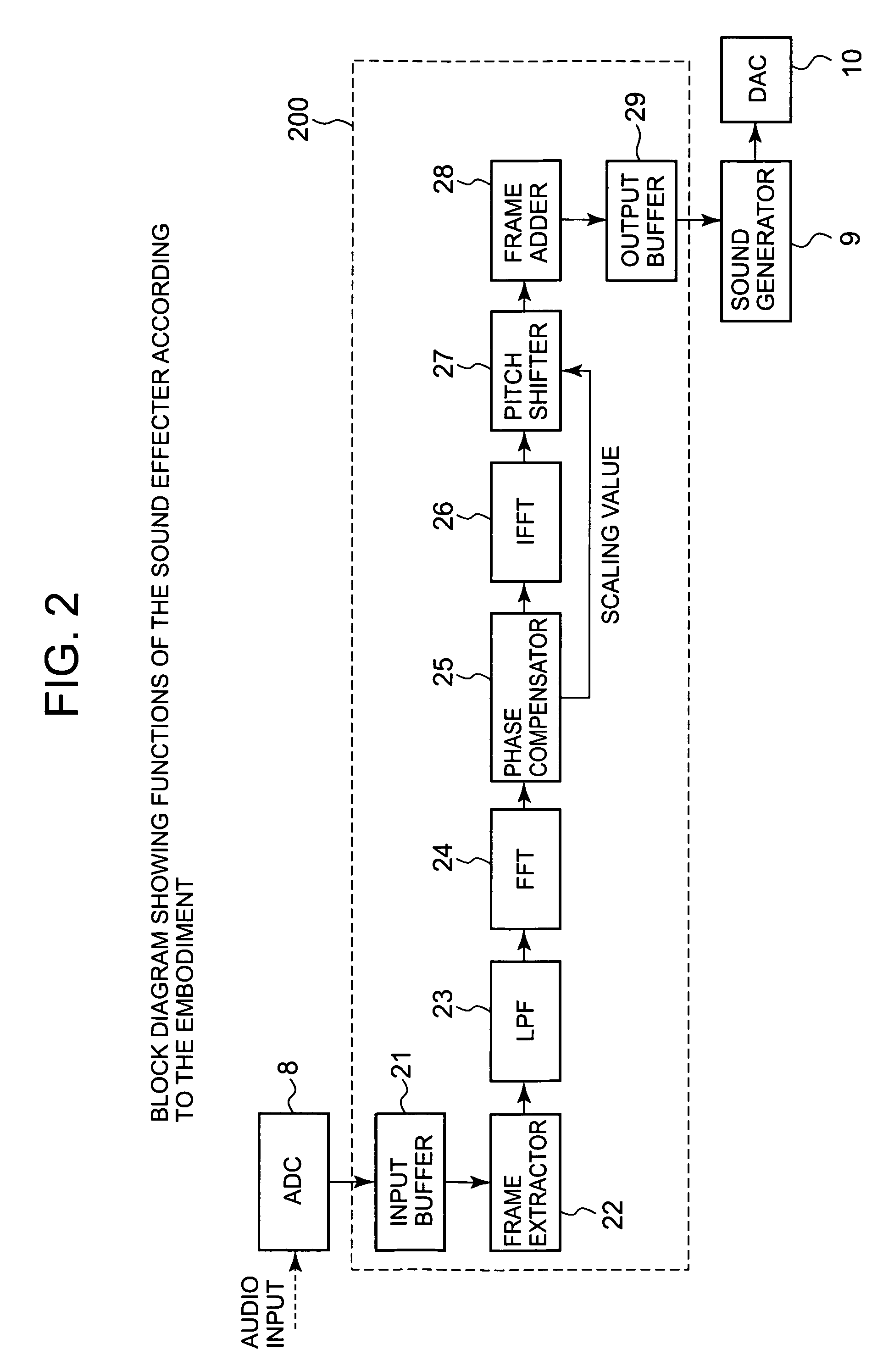
The present invention provides a technique for shifting pitch to target pitch without detecting the original pitch directly, and for extracting the pitch of the audio waveform exactly. A phase compensator extracts 2 or more frequency channels each having frequency components of a harmonic overtone whose frequency is 1 or more times as higher than frequency of a fundamental tone of the original sound, from the frequency channels from which the frequency components are extracted by fast Fourier transform. The phase compensator calculates a scaling value to be used for converting the fundamental tone to another target fundamental tone, and performs phase compensation in accordance with the scaling value. A pitch shifter performs pitch scaling in accordance with the scaling value onto the audio data resultant from inverse fast Fourier transform onto the phase compensated frequency components. Thus, audio data representing the target fundamental tone are generated.

Description

[0001]This application is based on Japanese Patent Application No. 2005-54481 filed on Feb. 28, 2005, including the specification, claims, drawings and summary thereof. The disclosure in Japanese Patent Application No. 2005-54481 is incorporated herein by reference in its entirety.FIELD OF THE INVENTION[0002]The present invention relates to a sound effecter which analyzes first audio waveform and generates second audio waveform by applying sound effect onto the first audio waveform based on the analysis.DESCRIPTION OF THE RELATED ART[0003]There are various sound effectors to generate sounds onto which sound effects are applied after analyzing audio waveform of the original sounds. Some of them have a pitch shifter function which shifts pitches of fundamental tones that appear in the waveform. Japanese Patent No. 2753716 is an example of one such sound effecter in the prior art.[0004]Such a sound effecter usually shifts pitch to generate effected waveform in order to adjust the pitch...

Claims


Application Information

Patent Timeline
Patent Type & Authority Patents(United States)
IPC IPC(8): G10H7/12H02M5/297G10L21/007G10L21/013G10L25/90
CPCG10H1/20G10H1/366G10H2210/066G10L25/90
Inventor SETOGUCHI, MASARU
Owner CASIO COMPUTER CO LTD
Learn More