
Prehensor device and improvements of same

Inactive Publication Date: 2008-03-11
INVISIBLE HAND ENTERPRISES LLC
View PDF21 Cites 50 Cited by
  • Summary
  • Abstract
  • Description
  • Claims
  • Application Information

AI Technical Summary

Benefits of technology

[0029]In accordance with still other embodiments of the present invention, the digits may include a replaceable digit portion to facilitate providing a replaceable end portion without having to dismantle the prehensor to replace the digit. More particularly, a digit may include an end portion that can be easily removed and replaced with a substitute end portion.
[0031]In accordance with yet other embodiments of the present invention, a tendon is provided that includes a low friction exterior jacket and a high tensile strength, low-creep interior core. The tendon is used within the prehensor, and facilitates rotation of the digits.

Problems solved by technology

While a number of prosthetic devices have been developed to assist these individuals, their use is not wide-spread due, at least in part, to the poor performance and design of existing prosthetics and prehensors.
Unfortunately, electronic systems are very expensive.
In addition, electronic systems can be unrealistically heavy and suffer from inadequate battery life.
Unfortunately, since gripping an object with a voluntary opening prehensor is passive, i.e., the wearer is not expending energy to maintain the grip, the wearer has limited, if any, control over the amount of force exerted on the object.
Gripping forces needed to lift heavy objects are excessive for small or lightweight fragile objects.
Conversely, the correct gripping force needed to lift a light object will usually be inadequate for heavier objects.
Third, by requiring that the wearer only exert the amount of energy necessary to attain the gripping force required to grasp an object, voluntary closing prehensors conserve a large amount of the wearer's energy.
Any excess energy used to open the digits is wasted.
While Radocy et al. provide a locking pawl to assist the wearer in maintaining a grip on an object, unfortunately, Radocy et al. require that the wearer manually actuate and release the locking pawl, a known safety hazard.
Unfortunately, Freeland does not provide an energy efficient device capable of assisting a wearer in maintaining a grip on an object.
Body-powered prosthesis users, in contrast, must consciously generate control cable tension by harnessing unrelated body motions (e.g. scapular abduction, shoulder elevation, elbow flexion); moreover, they can only maintain useful tension levels over relatively short cable excursions.
A simple mechanical lever arrangement offering only a single, fixed mechanical advantage is inherently incompatible with these opposing functional requirements.
That is, it is mechanically impossible for a drive mechanism using a single fixed lever to meet these dual operating requirements.
Some prior art devices attempt to compromise and skirt this functional problem using “average” lever ratios between 0.4 to 0.5, but this sets the device up to deliver poor to marginal performance in both grasping regimes.
Nevertheless, terminal devices using them are inherently inefficient designs.
Large gripping forces and proprioceptive feedback make voluntary closing units desirable and intuitive to operate, but when not engaged in grasp, they are open with the digits apart, making them prone to strike doorframes, furniture, and the user's thigh.
Moreover, existing individual voluntary opening or voluntary closing devices do not allow the wearer to changes modes between the functions.
For example, if a user were to fall while wearing a prehensor gripped to a railing, the user may suffer significant bodily harm if the prehensor were to maintain grasp of the railing throughout the entire event of the user falling.
Existing cables fabricated from steel or other metal alloys do not possess these qualities.
Digits are also frequently and permanently soiled and degraded by common chemicals, such as gasoline and cleansers.
More particularly, under a variety of circumstances, the digits of a prehensor may be exposed to or become contaminated with unsanitary matter.

Method used


Image

  • Prehensor device and improvements of same
  • Prehensor device and improvements of same
  • Prehensor device and improvements of same

Examples


Embodiment Construction

Variable Mechanical Advantage

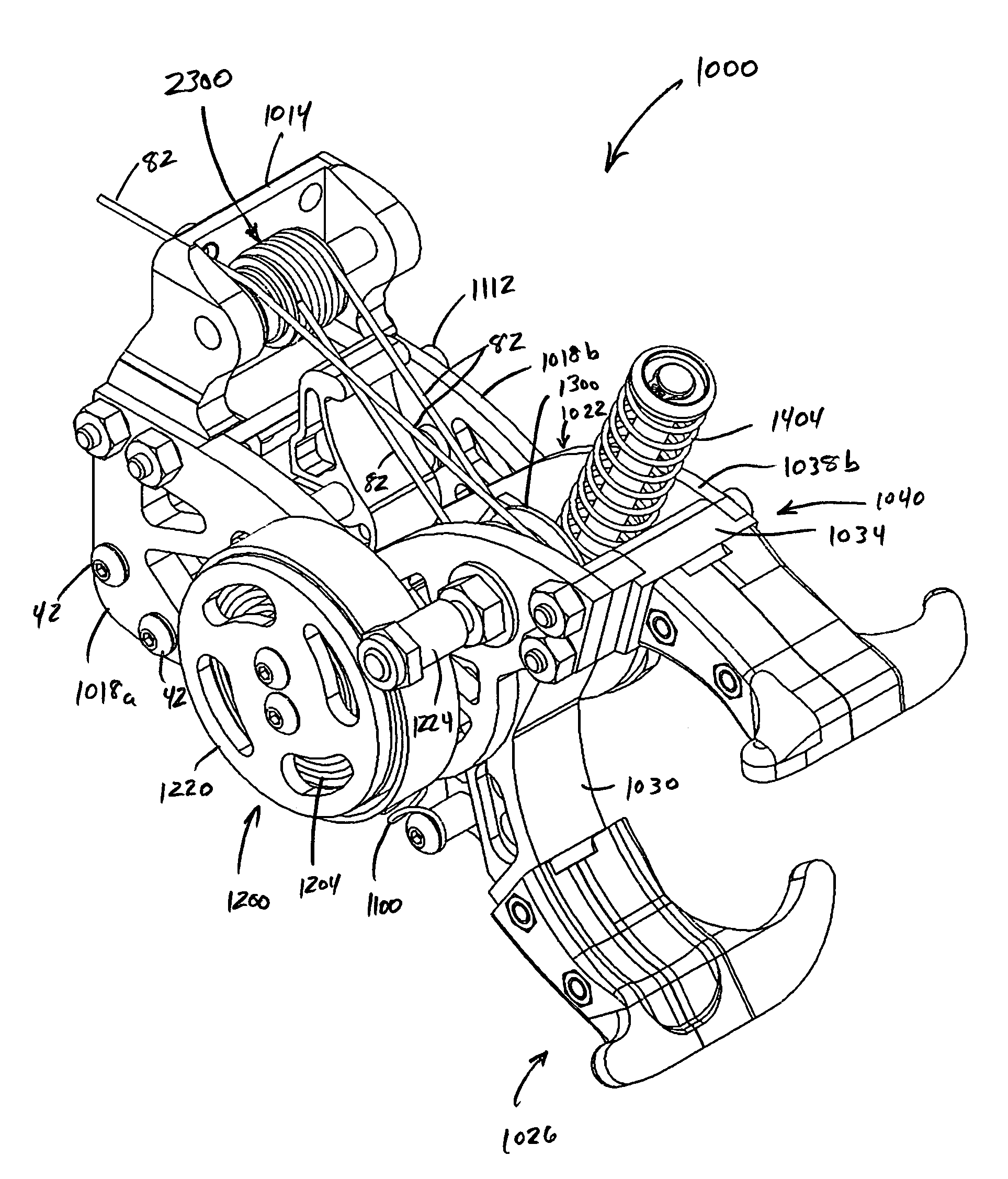
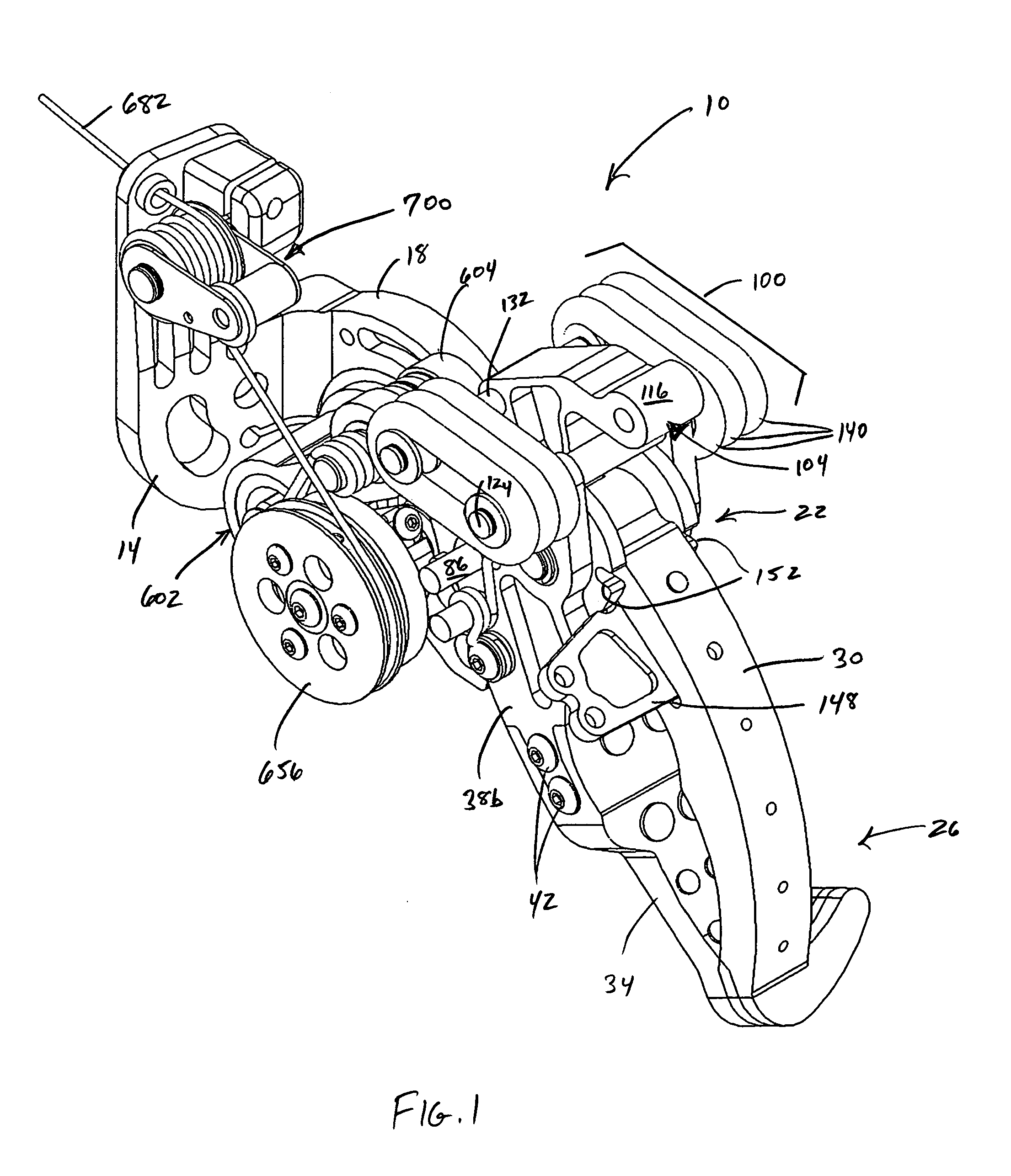
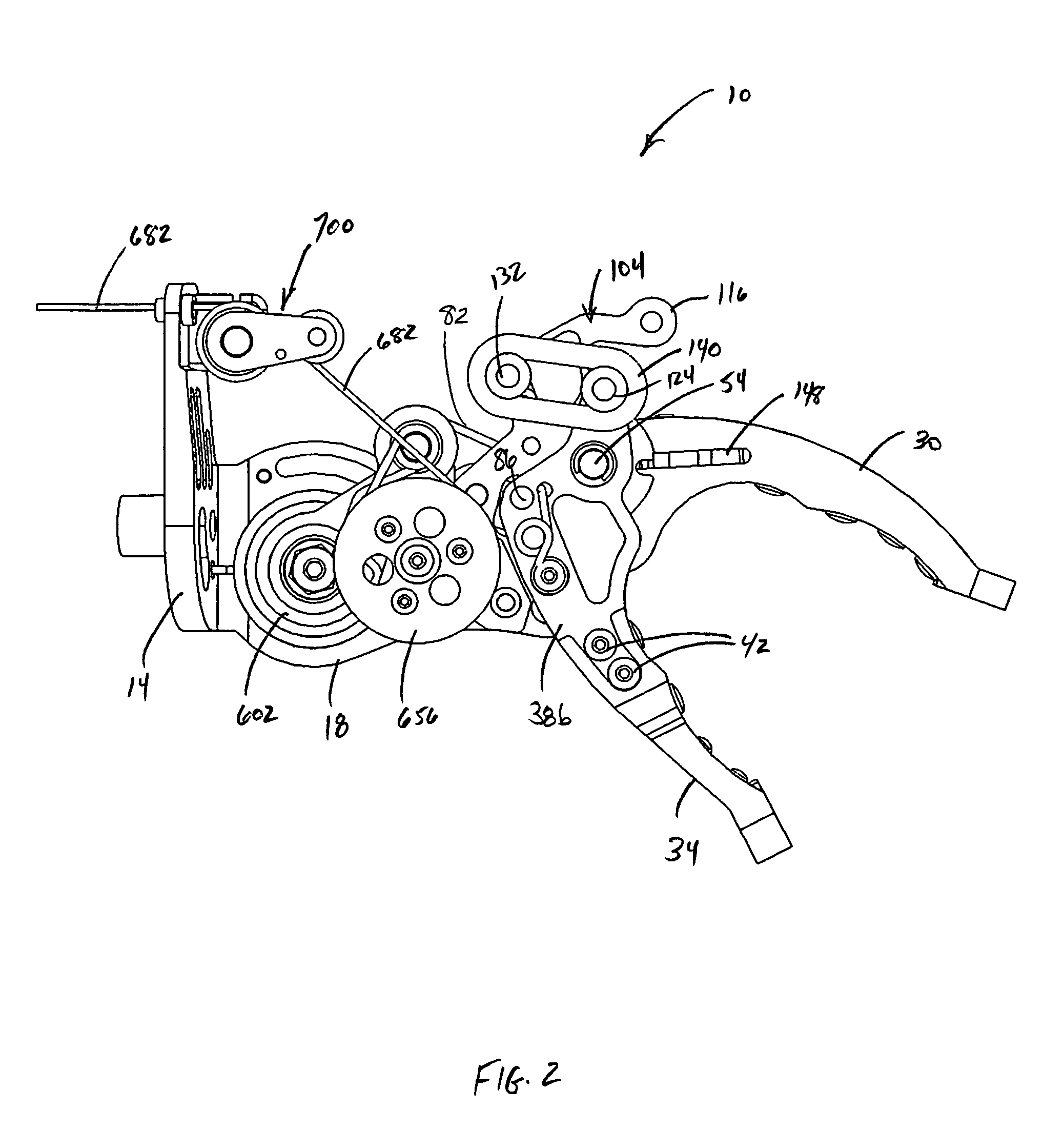
[0069]In accordance with embodiments of the present invention, a prehensor device may include a variable mechanical advantage (also referred to herein as “VMA”) mechanism. As described below, the VMA mechanism may comprise a brake assembly, or alternatively, the VMA mechanism may comprise a brakeless assembly. Both the brake and brakeless assemblies take energy they receive from the user as cable input, (i.e., force and displacement), and transform it into either: (1) low-force / high-displacement output used to adjust the space between the prehensor digits; or (2) high-force / low-displacement output to provide large traction forces to objects squeezed by the digits.

VMA with Brake Assembly

[0070]The following paragraphs describe a prehensor device that utilizes a brake assembly interconnected to the prehensor to provide a mechanism for allowing a user of the prehensor to first grasp an object and then apply a tighter gripping force. The brake assembly is the...


PUM

PropertyMeasurementUnit
Forceaaaaaaaaaa
Mechanical propertiesaaaaaaaaaa
Tensionaaaaaaaaaa

Abstract

A prehensor is provided comprising embodiments of a variable mechanical advantage mechanism, the prehensor including a first mechanical advantage for sizing an object, and a second mechanical advantage for gripping the object. Embodiments of the variable mechanical advantage mechanism include a brake assembly and multiple embodiments of a brakeless assembly. Additionally, multiple embodiments of a selectable voluntary opening / voluntary closing mechanism are provided, whereby a single prehensor can be switched back and forth between a voluntary closing mode and a voluntary opening mode. Additional embodiments include a safety clutch, an improved prehensor tendon, replaceable digits, and self decontaminating digits.

Description

CROSS REFERENCE TO RELATED APPLICATION[0001]The present application claims the benefit of U.S. Provisional Application No. 60 / 536,667 filed on Jan. 14, 2004, the entire disclosure of which is incorporated herein by reference in its entirety.STATEMENT REGARDING FEDERALLY SPONSORED RESEARCH OR DEVELOPMENT[0002]The U.S. Government has a paid-up license in this invention and the right in limited circumstances to require the patent owner to license others on reasonable terms as provided for by the terms of Contract No. Prime Contract ID 2R44 HD39046-02, Contract No. 4553, awarded by the National Institute of Health and National Institute of Child Health and Human Development.FIELD[0003]This invention relates generally to a prehensor and improvements related thereto, the improvements including embodiments comprising variable mechanical advantage mechanisms, and / or a selectable voluntary opening / voluntary closing mechanism, and / or a safety clutch, and / or a tendon, and / or replaceable digit ...

Claims


Application Information

Patent Timeline
IPC IPC(8): B25J15/08A61F2/54
CPCA61F2/588B25J9/104B25J15/0206A61F2002/30067A61F2002/5007A61F2002/5075A61F2002/5093A61F2250/0092A61F2310/00616
Inventor VEATCH, BRADLEY DELTONSCOTT, JOSEPH DAVID
Owner INVISIBLE HAND ENTERPRISES LLC
Learn More