
Atomizer for manual actuation

a technology of atomizer and atomizer, which is applied in the direction of burners, combustion types, combustion processes, etc., can solve the problems of affecting the atomizer's actuation accuracy, etc., and achieves the effect of reducing the difficulty of actuation for a person without practice, and reducing the usefulness of the container or the atomizer

Inactive Publication Date: 2008-03-11
BOEHRINGER INGELHEIM MICROPARTS
View PDF11 Cites 44 Cited by
  • Summary
  • Abstract
  • Description
  • Claims
  • Application Information

AI Technical Summary

Benefits of technology

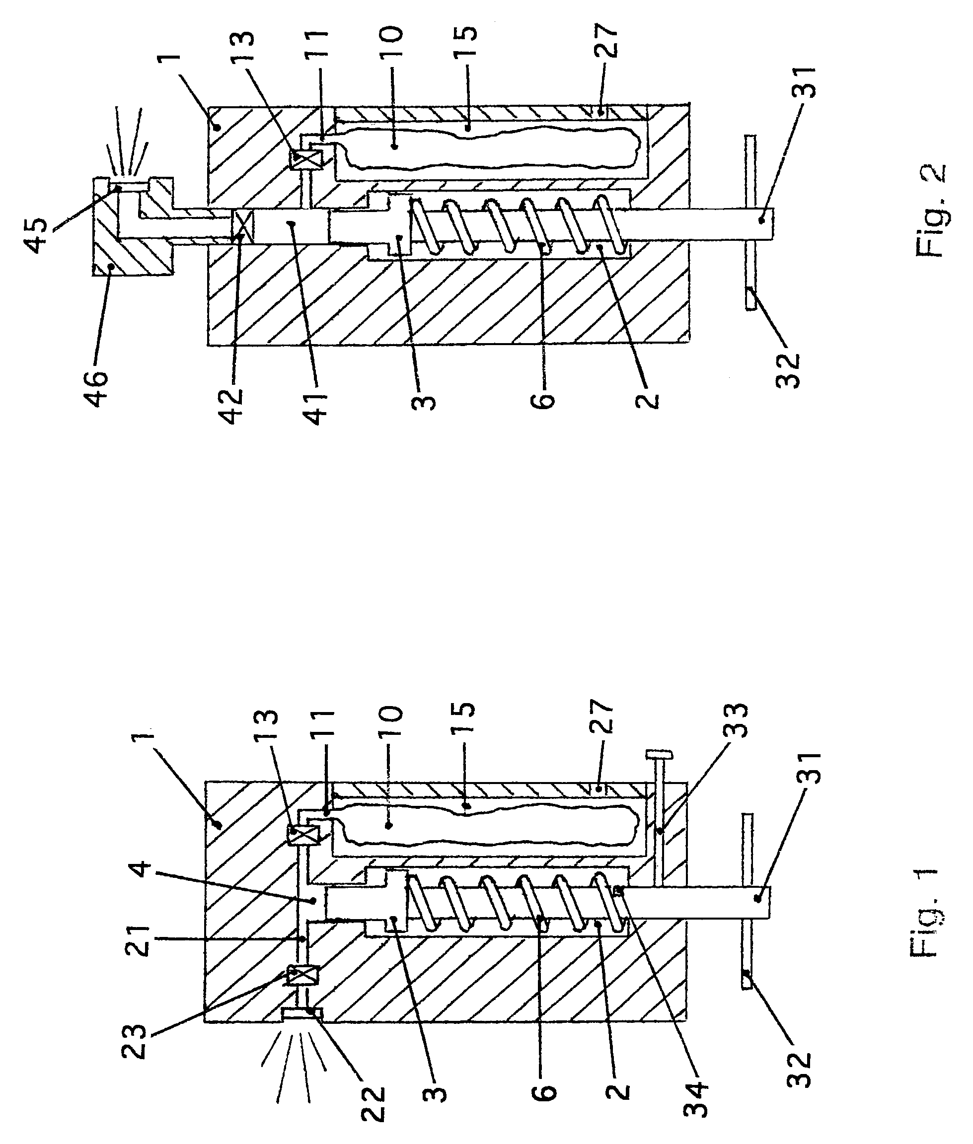
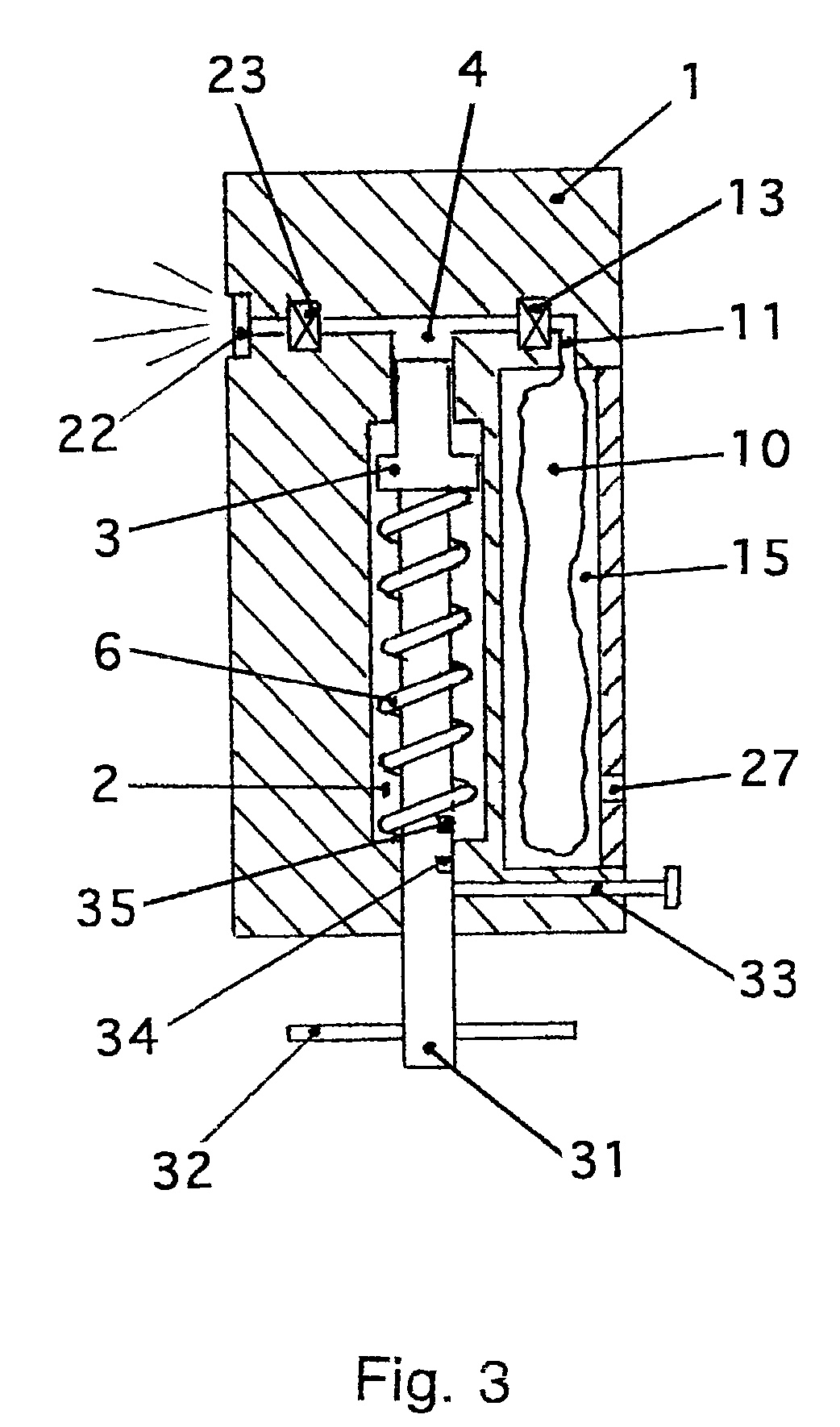
[0033]The atomizer can include a valve at least in the intake duct, preferably an automatically operating valve. The automatic valve opens at low pressure as the piston is pulled out of the cylinder when stressing the working spring. This valve closes when the piston is pushed into the cylinder by the working spring, and the atomizing process begins. This valve prevents fluid from flowing back into the storage container during the atomizing process.
[0046]The atomizer of the present invention can provide the following advantages:
[0051]The atomizer can be manufactured in various versions and be adapted to the intended application purpose and for favorable handling.

Problems solved by technology

Known propellants include gases that are physiologically hazardous, pollute the environment, or are flammable.
If during storage of the container, which is generally filled partially with the fluid, or during usage of the atomizer, the valve on the container is not sufficient gas-tight and the gas pressure drops due to the partially leaking gas, the usefulness of the container or the atomizer can be limited.
Actuation of such an atomizer can be difficult for a person lacking practice when the atomized fluid is supposed to be deposited at a specified location (for example on the skin of the user).
Both features are difficult to reproduce.
However, the fluid droplets are difficult to precipitate from the air current onto a surface that meets with the aerosol-containing air current.

Method used


Image

  • Atomizer for manual actuation
  • Atomizer for manual actuation
  • Atomizer for manual actuation

Examples


Embodiment Construction

[0065]Referring now to the drawings, wherein like reference numerals designate identical or corresponding parts throughout the several views, an example of the present invention is described below referring to the figures.

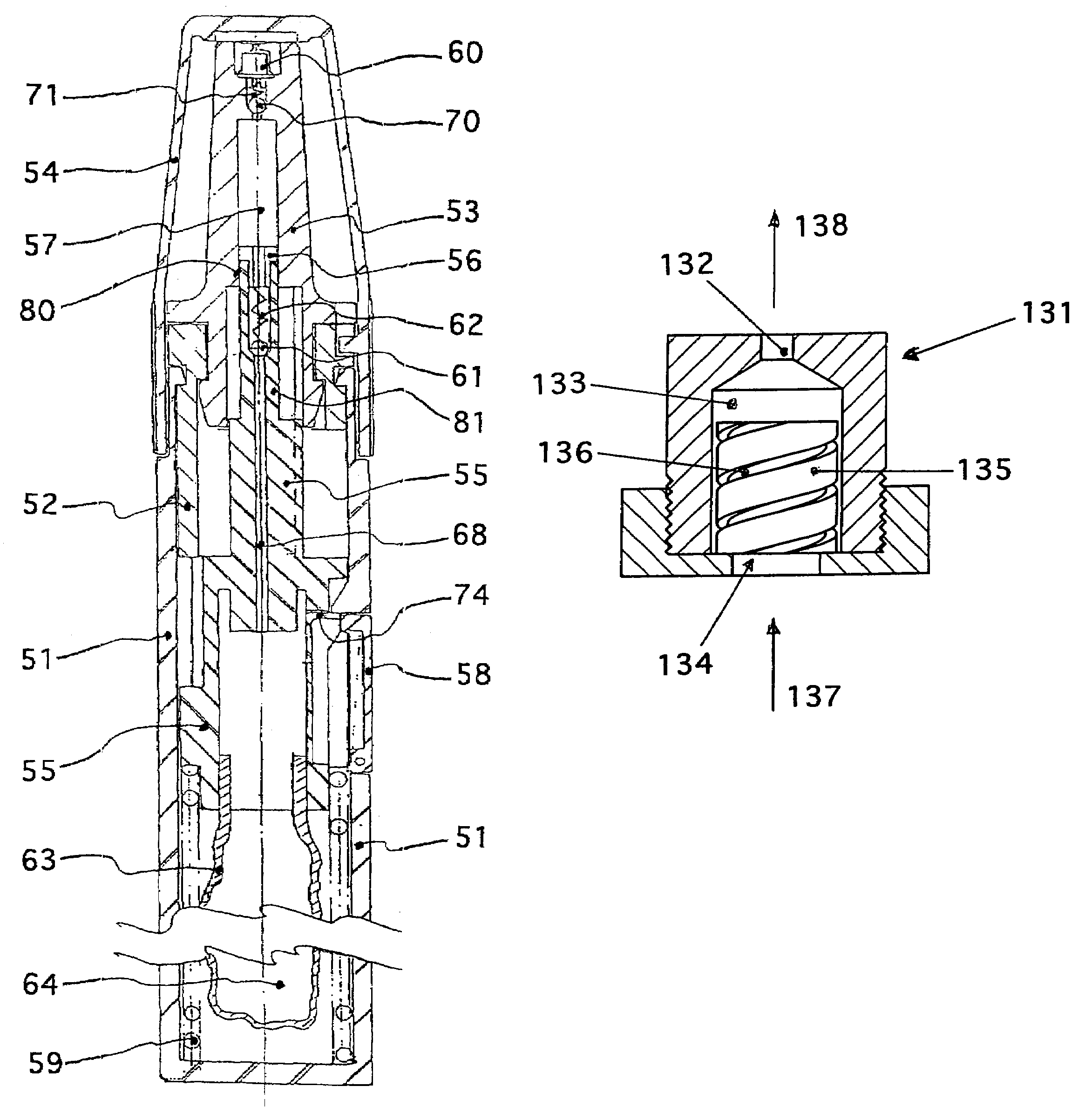
[0066]FIG. 1 shows a helical spring, which can be stressed manually with a handle that is attached to the outside of a housing by pulling the handle out, provided as a storage device for mechanical energy (working spring). A notch is provided in a rod that connects the handle with a piston, with which a spring-loaded stud engages at the end of the stressing process of the helical spring, thus keeping the rod in the position reached. Pulling the stud out of the notch triggers the atomization process. A collapsible bag can be used as a storage container for the fluid. FIG. 1 shows the atomizer in an intermediate stage that occurs between (i) when the piston is pulled out of the housing to a first stop and (ii) when the piston is pushed into the cylinder up to a secon...


PUM


Abstract

A fluid can be discontinuously atomized with an atomizer of the present invention. The atomizer can include a helical spring, disk spring or gas spring, acting as a pressure spring, as an energy storage device, a cylinder, piston, two ducts and two valves. Atomization can be initiated manually by triggering a locking mechanism. The energy storage device can be disposed outside a storage container for the fluid. The energy storage device can be provided mechanical energy manually. Via the piston, the stored energy can exert pressure onto the fluid in the cylinder, which ranges from 1 MPa to 5 MPa (10 bar to 50 bar). Distribution of the droplet size in the atomized jet can be independent from the level of experience and behavior of the person actuating the atomizer, and can be adjusted in a reproducible manner. The mean droplet diameter can be smaller than about 50 micrometers. The mass flow of the fluid through the nozzle can be less than about 0.4 g / s. The design and function of the atomizer can be adjusted to properties of the fluid, to a planned application, and to a desired manner for handling the atomizer.

Description

BACKGROUND OF THE INVENTION[0001]1. Field of the Invention[0002]The invention relates to an atomizer for a fluid whose droplets are precipitated onto a surface. The atomizer can atomize aqueous and non-aqueous fluids, emulsions and suspensions, solutions, dyes and oils. The atomizer can be miniaturized, and it can also contain micro-structured elements.[0003]The atomizer according to the present invention does not require a propellant gas, can be actuated manually, and can be adapted to the properties of various fluids that are to be atomized, as well as to the planned application of the atomized fluid.[0004]2. Description of the Related Art[0005]Atomizers are known where the fluid under pressure contains a propellant (e.g., a liquefied propellant gas) with which the fluid is atomized upon exiting through a nozzle, such as by the influence of the evaporating propellant. Known propellants include gases that are physiologically hazardous, pollute the environment, or are flammable. The...

Claims


Application Information

Patent Timeline
Patent Type & Authority Patents(United States)
IPC IPC(8): B05B1/34B05B17/04B05B9/08B05B11/00
CPCB05B1/3436B05B9/0883B05B11/3091B05B1/3447B05B11/1091
Inventor PETERS, RALF-PETEREICHER, JOACHIMHOLLMANN, HOLGERREINECKE, HOLGERDUNNE, STEPHEN TERENCE
Owner BOEHRINGER INGELHEIM MICROPARTS
Learn More