
Multi-layered electrodes and uses thereof

a multi-layer electrode and electrode technology, applied in the field of electrodes, can solve the problems of non-symmetrical current distribution, non-symmetrical current distribution is not desirable, burning and/or irritation of the skin,

Inactive Publication Date: 2008-03-04
POWER PAPER
View PDF14 Cites 22 Cited by
  • Summary
  • Abstract
  • Description
  • Claims
  • Application Information

AI Technical Summary

Benefits of technology

This design achieves higher current output and voltage support with symmetrical current distribution, reducing the risk of skin irritation and enhancing drug delivery efficiency in transdermal systems.

Problems solved by technology

Electrical contacts must be placed on the same side as the insoluble electroactive material, resulting in non-symmetrical current distribution.
However, non-symmetrical current distribution is not desirable in for example transdermal delivery systems.
In such systems, if the current is not uniform, drug delivery may not be uniform and a concentrated current at one electrode point can cause burning and / or irritation of the skin.
However, vinyl web has relatively high sheet resistance and when an active electrode is not regular in shape and size, there is significant differences in the resistance along the length of the electrode, resulting in uneven current distribution.

Method used


Image

  • Multi-layered electrodes and uses thereof
  • Multi-layered electrodes and uses thereof
  • Multi-layered electrodes and uses thereof

Examples


example 1

A Method of Making a Higher Powered Electrode with Uniform Current Distribution and High Capacity

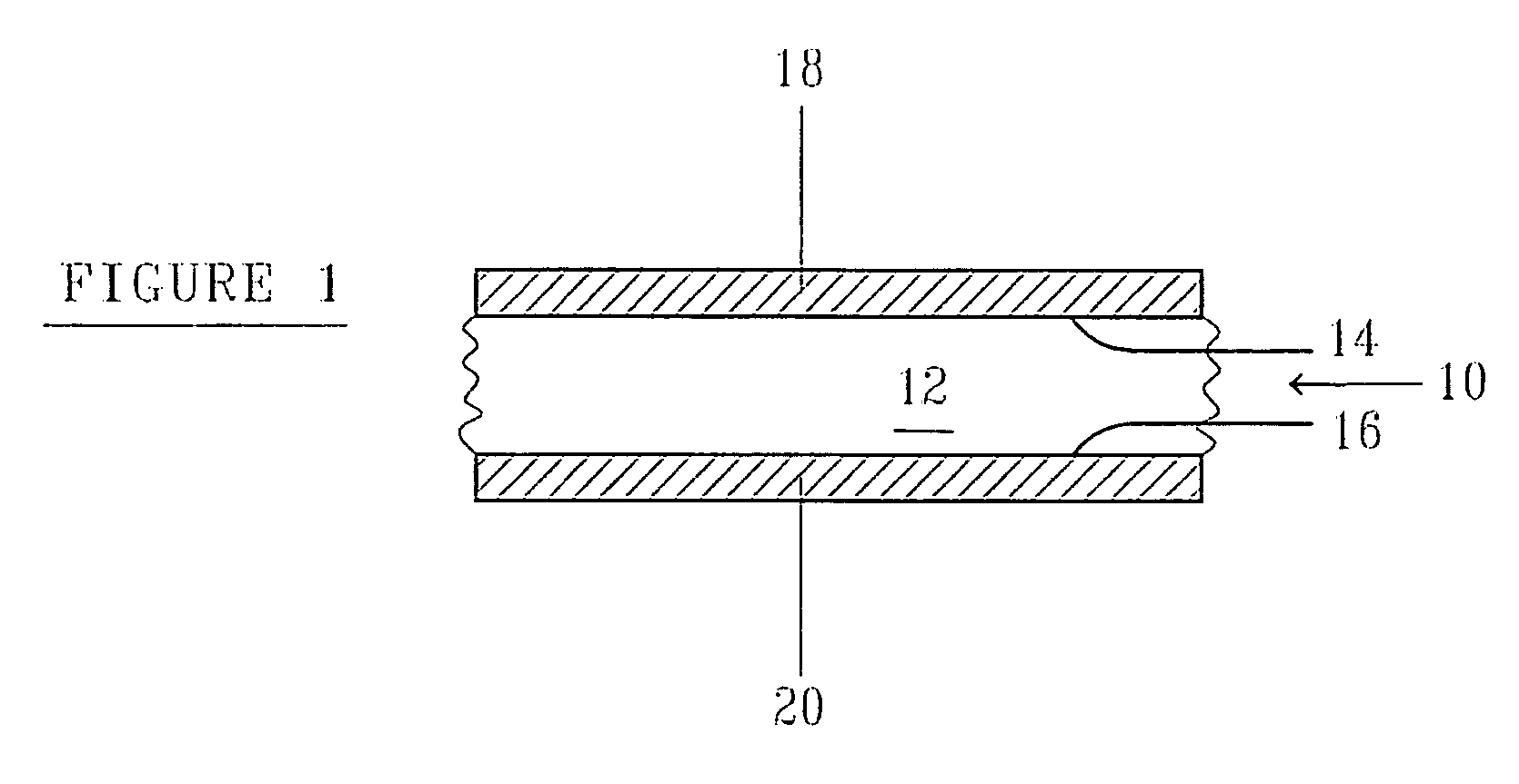
[0062]One side of a vinyl web was coated with silver using a printing technique, using draw down equipment. The silver ink applied was Acheson silver ink, but any silver ink can be used. The silver ink was then dried using a suitable drying technique. The dry thickness of the silver layer was preferably a few microns, from about 2 to about 5 microns. After drying of the silver layer, the second surface of the vinyl web substrate was coated with zinc ink. The zinc ink was composed of a high purity zinc powder, of about greater than 95% purity, a suitable resin / solvent system and graphite conductive particles. The vinyl web was coated with the zinc ink using a draw down applicator. The zinc layer was then dried using a suitable drying technique. After drying, the thickness of the zinc layer was about 25 microns. The capacity of the electrode can be controlled by the loading weight (thickne...

example 2

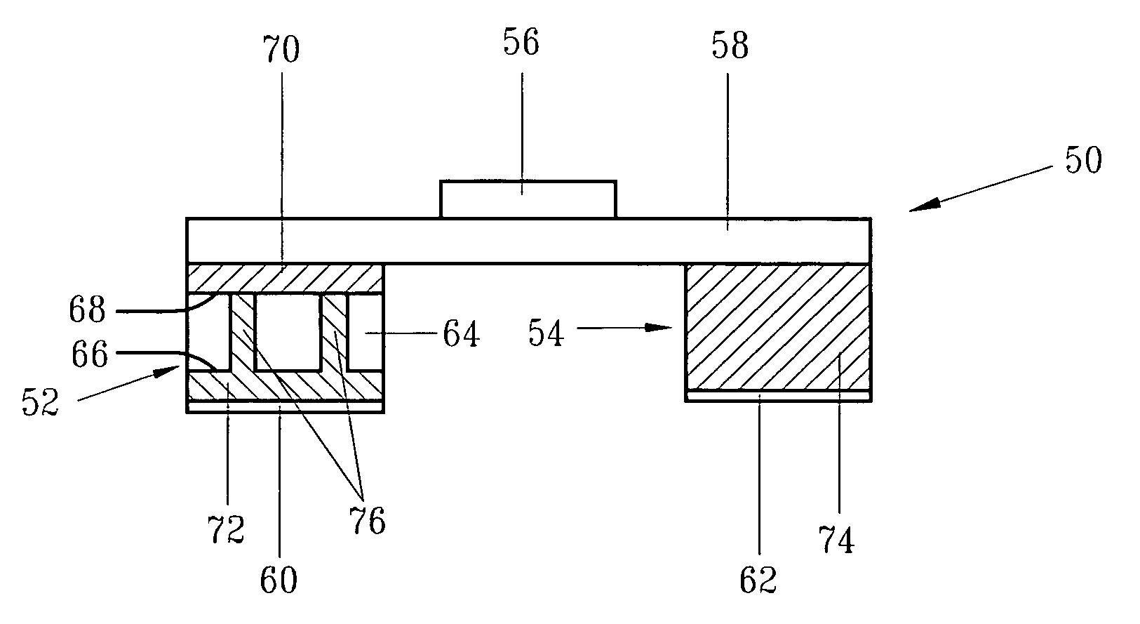
[0063]In one non-limiting example of the electrode of the present invention, the electrode was used as part of a dermal patch. The anode of the patch included a vinyl film coated on one side with relatively pure zinc, resulting in a capacity of about 18 mA minute / cm2. The backside of the vinyl film was coated with a layer of silver to improve conductivity and ensure homogeneous current distribution along the electrode, which in one non-limiting example was linear shaped. The cathode included a vinyl film coated with silver / silver chloride, resulting in a capacity of 18 mA minute / cm2.

example 3

[0064]Vinyl substrate was coated with a 20μ layer of 40% (% W) zinc ink. The sheet resistance was 10.7Ω / square. The resistance of a strip 0.5 mm wide and 100 mm long was 270Ω. For comparison a vinyl substrate was coated with a 20μ layer of 40% zinc ink (% W) and coated from the backside with a 5μ layer of silver ink. The sheet resistance was 0.5Ω / square. The resistance of a strip 0.5 mm wide and 100 mm long was 1.2Ω. Therefore, it could be seen that the coating of a conductor, such as silver on the backside of the vinyl substrate resulted in a significantly lower sheet resistance, which is indicative of more uniform current distribution.


PUM

PropertyMeasurementUnit
working voltageaaaaaaaaaa

Abstract

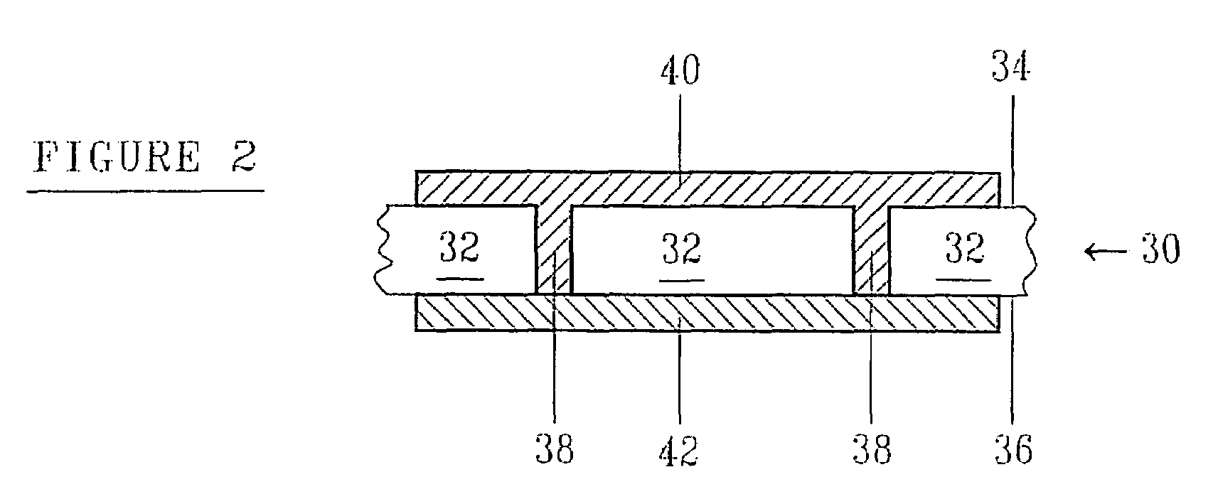
The present invention is of an electrode comprising an electrode substrate, wherein the electrode substrate has an electrode side and a back side; a conductive material layer disposed on the back side of the electrode substrate; and an insoluble electroactive material disposed on the electrode side of the electrode substrate. The electrode substrate can be a conductive substrate or a non-conductive substrate. In an embodiment wherein the substrate is a non-conductive substrate, the electrode can include vias which extend from the electrode substrate backside to the electrode side of the substrate. In some embodiments, the electroactive material is zinc and the conductive material is silver. The present invention provides an electrode with improved current distribution and high capacity, which can provide higher current and / or higher voltage. In addition, the present invention provides a dermal patch, which includes a higher powered, high capacity electrode with uniform current distribution. Still further the present invention provides methods of making the electrode and of attaching the electrode to a power source.

Description

[0001]This application claims priority to U.S. Provisional Application Ser. No. 60 / 582,803, filed Jun. 28, 2004 and incorporated by reference herein in its entirety.FIELD OF THE INVENTION[0002]The present invention relates to electrodes and uses thereof.BACKGROUND OF THE INVENTION[0003]Numerous types of electrodes are typically used in a variety of diverse applications. Electrode structure and characteristics are usually dependent on the application of the electrode.[0004]One type of electrode of the background art comprises a non-conductive substrate layer, such as a polyester layer with an insoluble electroactive material coated on at least one side. Electrical contacts must be placed on the same side as the insoluble electroactive material, resulting in non-symmetrical current distribution. However, non-symmetrical current distribution is not desirable in for example transdermal delivery systems. In such systems, if the current is not uniform, drug delivery may not be uniform and...

Claims


Application Information

Patent Timeline
Patent Type & Authority Patents(United States)
IPC IPC(8): A61N1/04A61F13/00A61K9/28A61N1/30C25B11/00H01M4/04H01M4/36H01M4/38H01M4/42H01M4/58H01M4/66H01M4/70H01M14/00
CPCA61F13/00H01M14/00A61N1/0436A61N1/0492H01M4/0404H01M4/364H01M4/366H01M4/38H01M4/42H01M4/582H01M4/661H01M4/663H01M4/70A61N1/042A61N1/0428A61N1/0456A61N1/05A61N1/0412Y02E60/10
Inventor NITZAN, ZVILUSKI, SHALOMMOSHKOVICH, MORDECHAY
Owner POWER PAPER
Learn More