Electric-powered fishing reel
a technology of electric motors and reels, applied in fishing reels, applications, applications, etc., can solve the problems of complex speed change operation, time-consuming, and insufficient torque during low speed rotation, and achieve the effects of simple structure, low noise of gear mesh, and comfortable high-speed winding
- Summary
- Abstract
- Description
- Claims
- Application Information
AI Technical Summary
Benefits of technology
Problems solved by technology
Method used
Image
Examples
first embodiment
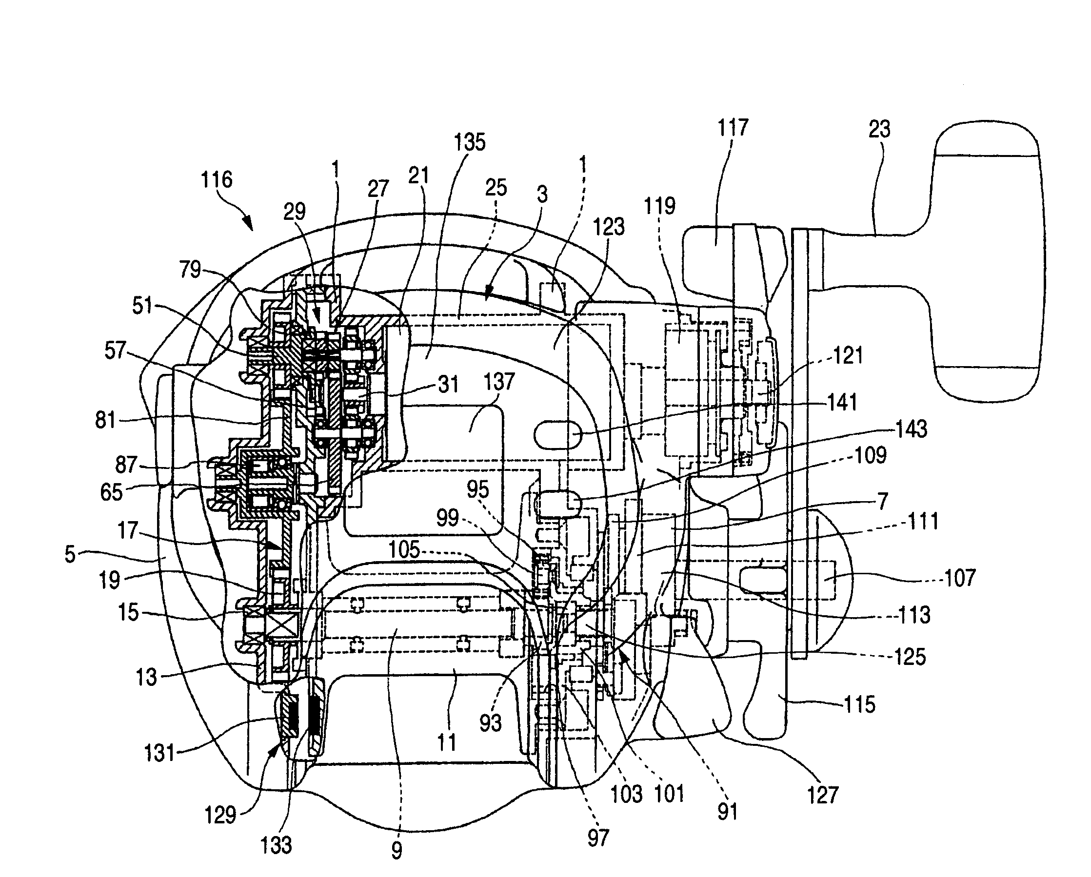
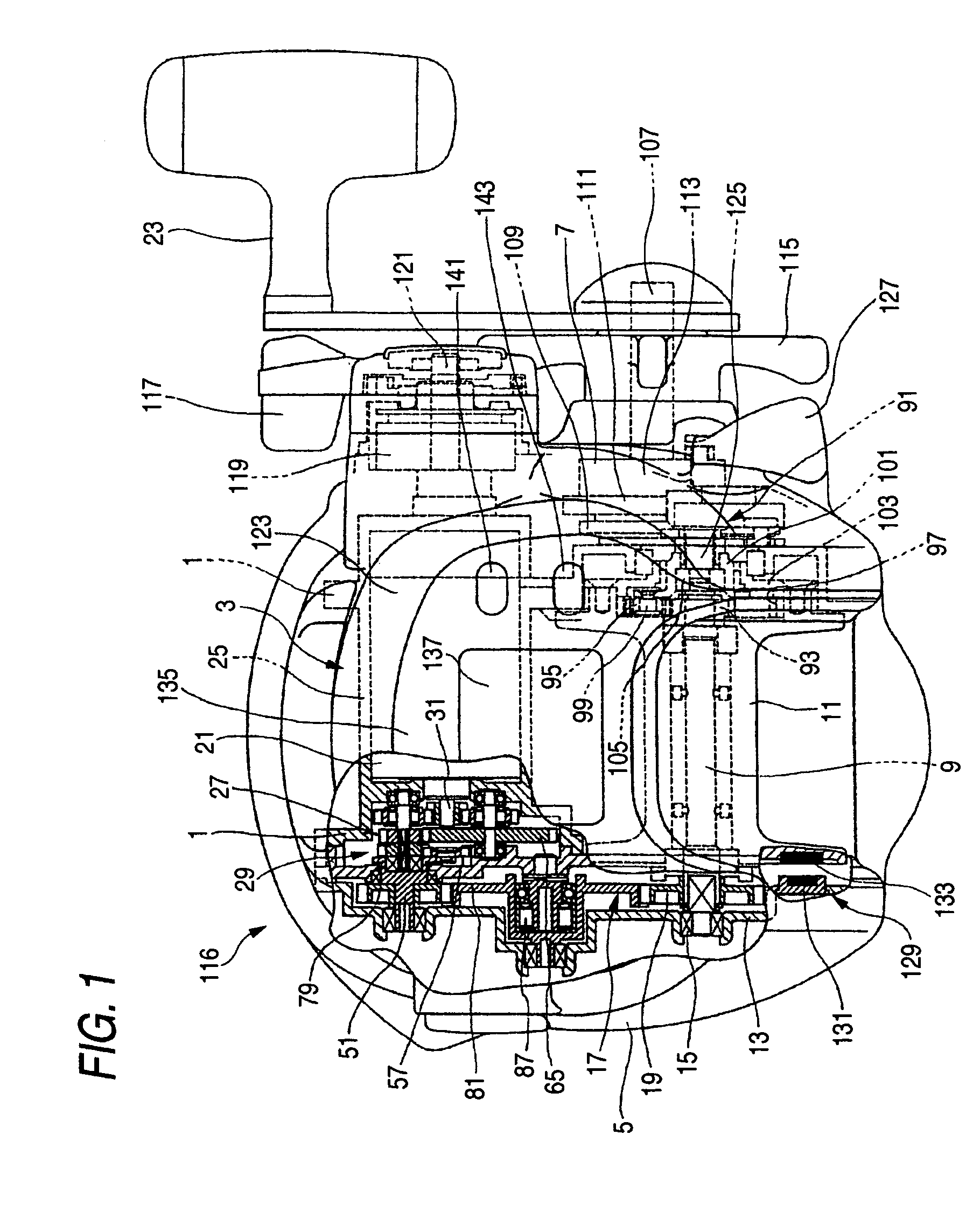
[0071]FIGS. 1 to 9 show an electrically-powered reel according to a first embodiment as in claim 1 and claim 2. In FIG. 1, reference numeral 1 denotes a frame of a reel body 3, and reference numerals 5 and 7 denote side plates secured to the left and right sides of the frame 1. A spool 11 is rotatably supported by a spool shaft 9 between both side plates 5 and 7.
[0072]The spool shaft 9 extends through the axis of the spool 11, and one end of the spool shaft 9 on the side of the side plate 5 is rotatably supported via a bearing 15 on a first set plate 13 which is integrally secured to the frame 1. A spool shaft drive gear 19 of a power transmission mechanism 17 which will be described later is nonrotatably fitted on the one end of the spool shaft 9.
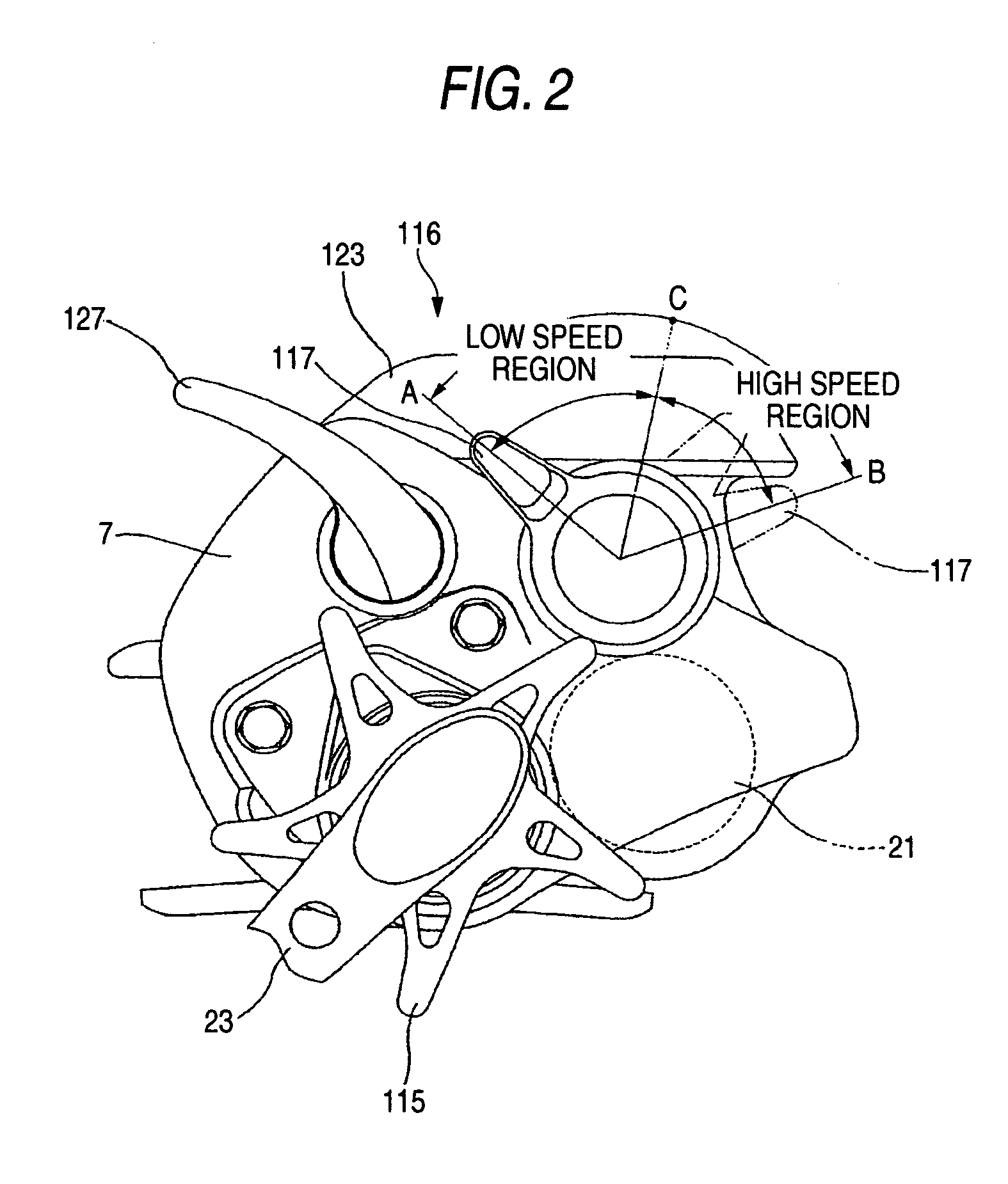
[0073]The spool 11 is constructed to wind a fishing line thereon by being rotated in the winding direction by the drive of a spool motor 21 and by the winding operation of a handle 23. As shown in FIGS. 1 and 2, the spool 11 is accommodate...
second embodiment
[0118]FIG. 10 shows an electrically-powered reel 151 according to a second embodiment as in claims 1 and 2. In the second embodiment, a slide switch is used as a motor output adjustment member in place of the above-mentioned power lever 117. Although the second embodiment of the invention will be described below with reference to the FIG. 10, the same reference numerals are used to denote the same constituent elements as those used in the first embodiment, and the description of the same constituent elements is omitted herein.
[0119]As shown in FIG. 10, a power switch 153 is fitted on the top section of the side plate 7 adjacently to the display 137 for sliding movement along a guide slit 155 in the forward and rearward directions of the reel body 3 between the motor stop position A and the maximum operation position B.
[0120]Similarly to the case of the first embodiment, the second embodiment is constructed so that when the power switch 153 is slid by half from the motor stop positio...
third embodiment
[0125]FIG. 11 shows an electrically-powered reel 171 according to a third embodiment as in claims 1 and 2. Japanese Patent No. 3,159,637 discloses an electrically-powered reel which includes, in addition to an electrical speed change unit using a power lever, a mechanical speed change unit which mechanically switches the rotational speed of a spool between a high speed state and a low speed state by turning on / off a part of a drive system of a speed reduction mechanism which reduces the rotational speed of a spool motor, so as to change the ratio of gear mesh, by the operation of a switching member (a manual external operation member). In the third embodiment, instead of the switching member, a speed change switching stopper 163 which is engaged with a ratchet gear 161 formed around the outer periphery of an internal gear 159 as shown in FIG. 11 is operated through the drive and control of a solenoid 165 by the microcomputer. The speed change switching stopper 163 is normally urged ...
PUM
 Abstract
Description
Claims
Application Information
 - R&D
- Intellectual Property
- Life Sciences
- Materials
- Tech Scout
- Unparalleled Data Quality
- Higher Quality Content
- 60% Fewer Hallucinations
Browse by: Latest US Patents, China's latest patents, Technical Efficacy Thesaurus, Application Domain, Technology Topic, Popular Technical Reports.
© 2025 PatSnap. All rights reserved.Legal|Privacy policy|Modern Slavery Act Transparency Statement|Sitemap|About US| Contact US: help@patsnap.com


