Flexible tubular device

a tubular metal and flexible technology, applied in the direction of flexible pipes, pipes, pipes/joints/fittings, etc., can solve the problems of system failure, reduced the ability to absorb other, torsional mode is, however, often unwanted, etc., and achieves less cost, increased life span, and lighter materials

Inactive Publication Date: 2008-02-26
NORSK HYDRO ASA
View PDF14 Cites 5 Cited by
  • Summary
  • Abstract
  • Description
  • Claims
  • Application Information

AI Technical Summary

Benefits of technology

[0013]One object of the present invention is to provide an improved design of a flexible device such as a bellows, for obtaining increased life span and / or obtaining the option of using alternative materials, compared to the known designs. Another object is to provide the option of using less costly materials and / or lighter materials.
[0015]All geometrical transitions and bends result in stress raisers and a design must be obtained where the magnitude of such unavoidable present stress raisers is reduced. Compared to the standard U-shaped convolution, the increased flexibility is achieved by making higher convolutions, without significantly increasing the convolution width. At the same time, having a smaller curvature in the top portion, thereby reducing the stress raisers for this region, reduces the total stress level during deformation of the convolution. The design with a curve having a curvature, which changes sign only once at a change position located between a top portion and an adjacent bottom portion, provides a smooth transition between the top and bottom portions. To minimize the stress level by the top portion, the length of the first section on the curve is at least 10% longer than the length of the second section on the curve, both sections extending from the locations where the curvature changes sign. In this way the locations, where the curvature changes sign, are shifted towards the bottom portions and thus provide a design with narrow bottom portions and wider, smooth top portions, which significantly reduces the overall stress level. This provides an improved design of the flexible device whereby increased life span is obtained. Also, the improved design provides options to use alternative materials, compared to the known designs, e.g. aluminium instead of stainless steel. In this way, less costly materials and / or lighter materials may also be used.
[0016]In another embodiment the length of a first section on the curve may be at least 50% longer than the length of a second section on the curve, said first section extending from one change position to an adjacent change position via a top portion, and said second section extending from one change position to an adjacent change position via a bottom portion. This gives further priority to the shape at the top portions and further reduces the overall stress level.
[0017]In a further embodiment the curvature of the convolutions may numerically be at least 20% smaller by the top portions than by the bottom portions, which results in a reduction of the overall stress level.
[0019]In yet a further embodiment the curve between a bottom portion and an adjacent bottom section may have one global maximum placed at the top portion and two global minima, said minima being placed by the bottom portions, and the curvature by the global maximum of the curve may have a local minimum. This provides an improved shape with significantly reduced effect of the present stress raisers, and a high degree of utilization of the material.
[0020]In a still further embodiment the curvature of the curve between a top position and an adjacent bottom section has a local minimum. This provides a smooth shape without abrupt geometrical changes.

Problems solved by technology

Unless some compensation for these dimensional changes is provided, high stresses will be induced in the equipment or the piping and might lead to system failure.
The torsional mode is, however, often unwanted because it destabilises the convolution in a way that reduces its ability to absorb other modes.
Within the industry, it is commonly accepted that the leading cause of failure for bellows is due to fatigue or one-time damage during installation.
In both cases the bellow is stressed beyond a characteristic threshold value, which leads to failure.
The literature is, in addition, limited with regard to estimating fatigue data for calculating the lifetime of current standard spans, e.g. the data varies greatly when the pitch-height convolution ratio varies.
The helical corrugations cause twisting of the tube when the tube is subjected to bending.
In many automotive applications, fuel lines, brake lines etc. the ends of tubes / pipes are fixed, but vibrations and other movements will create repeated bending and thereby twist.
However, the twist is locked due to the fixed ends whereby significant stresses are caused.
Repeated stresses lead to metal fatigue and component failure.
Although the disclosed shape may obtain high flexibility, the stress-raisers will decrease the live span under repeated loading due to fatigue.

Method used


Image

  • Flexible tubular device
  • Flexible tubular device
  • Flexible tubular device

Examples


examples

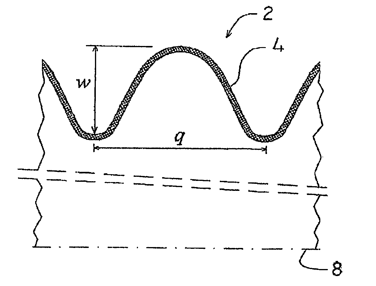
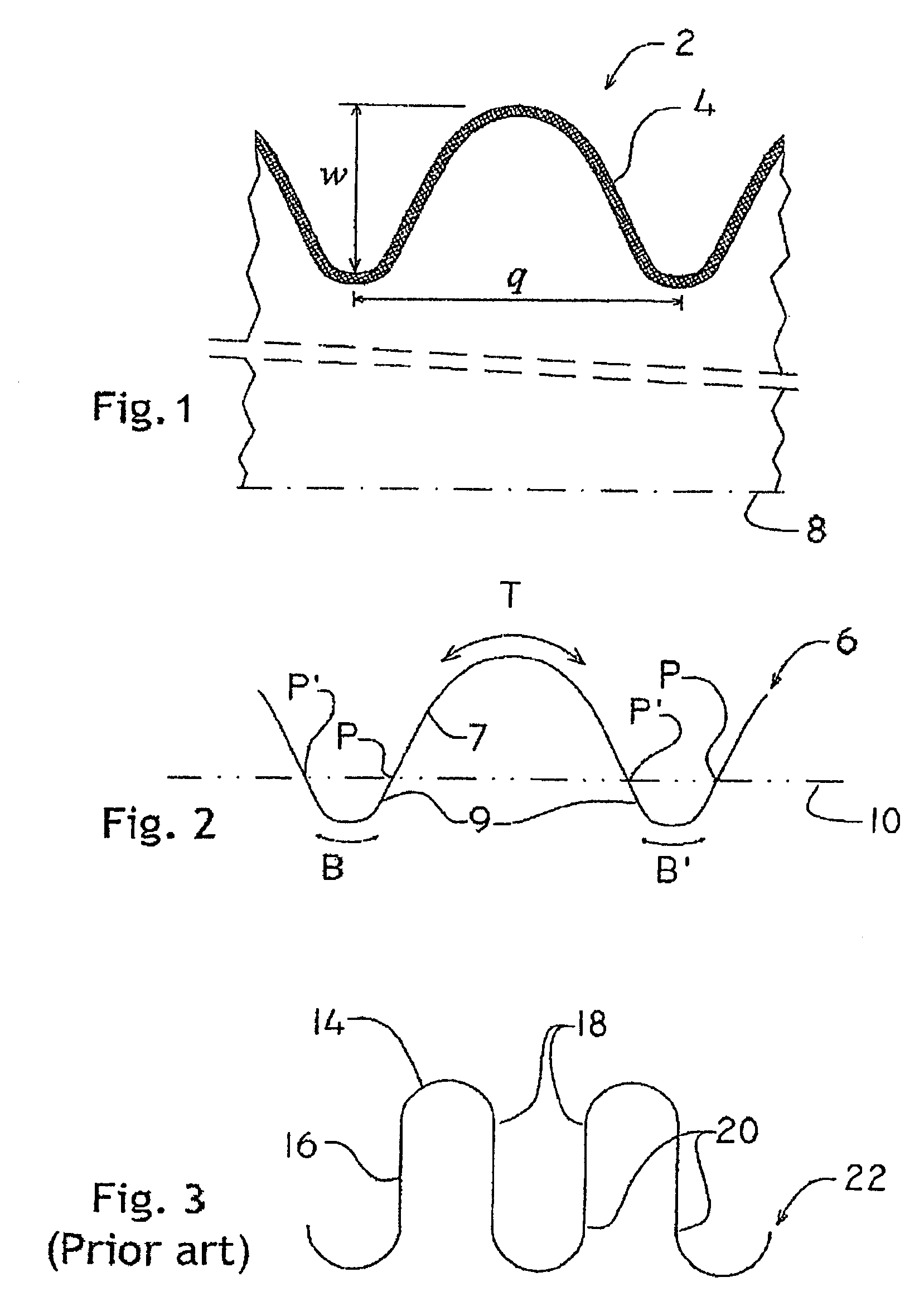
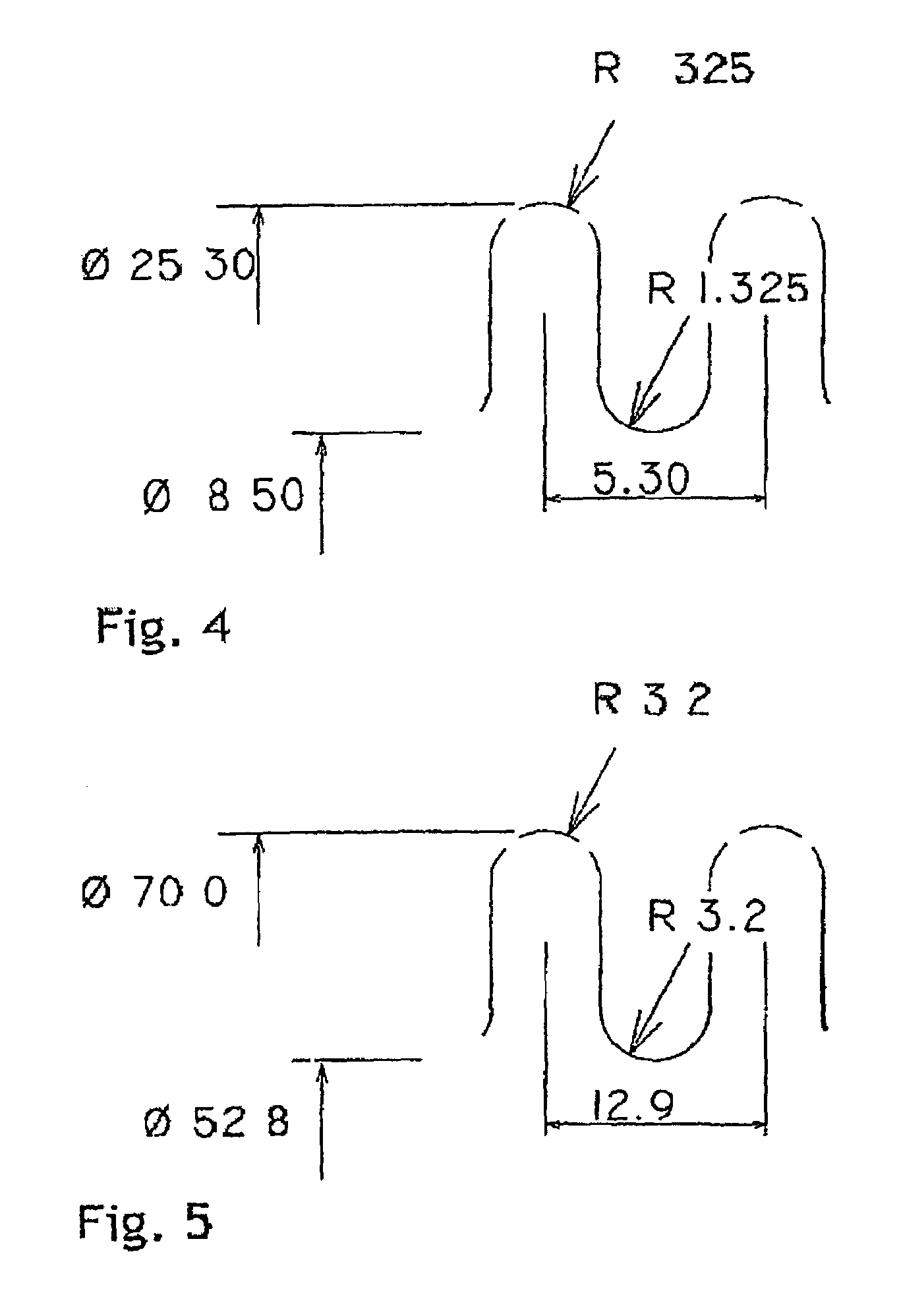
[0038]FIGS. 6 through 12 show seven examples. labeled Example 1 through Example 7, respectively, of designs in accordance with the present invention and discussed below. Table 1 displays the internal diameters, wall thicknesses and material for the examples. In each example the design of one convolution is given, as well as the corresponding curvature relating to the design. The design and curvature are presented as a series of points, which are to be understood as points on a smooth curve through said points, said curve not being depicted. In each example the design of the convolutions is presented by circular marks whereas the curvature is presented as triangular marks. The horizontal axis displays the width of a convolution from one side to another, starting at a bottom portion 6, see FIG. 2, and ending at a bottom portion B′ via one top portion T. The vertical axis on the left side depicts the height. Both height and width are in millimeters. The vertical axis on the right side ...


PUM


Abstract

A flexible tubular device that includes a metal wall in which are formed corrugated convolutions that define corrugated outside and inside surfaces of the device. The convolutions are perpendicular to a longitudinal axis of the device, and each convolution has oppositely-disposed rounded top and bottom portions. The outside surface of the device has first and second sections with change positions therebetween. Each first section extends from one of the change positions to another via one of the top portions. Each second section extends from one of the change positions to another via one of the bottom portions. The length of each first section is at least 10% longer than the length of each second section. The outside surface has a curvature that is numerically smaller at the top portions than at the bottom portions, and changes sign only once at each change position.

Description

CROSS REFERENCE TO RELATED APPLICATIONS[0001]This application claims the benefit of International Application No. PCT / EP2003 / 013044 filed Nov. 17, 2003, having a priority claim to Norwegian patent application number 20025536 filed Nov. 18, 2002.BACKGROUND OF THE INVENTION[0002]The invention relates to a flexible, tubular metal device e.g. a bellows with an internal diameter up to 60 millimeters, said device comprising one or more corrugated convolutions, said convolutions having an overall bell-like shape with rounded top portions and rounded bottom portions, where the curvature of the outside surface of the convolutions is numerically smaller at the top portions than at the bottom portions, said curvature being derived from a curve defined as the intersection of the outside surface of the device and a plane through the longitudinal axis of the device, and where the curvature of said curve changes sign only once at a change position located between a top portion and an adjacent bott...

Claims


Application Information

Patent Timeline
IPC IPC(8): F16L11/00F16L11/15F16L27/11
CPCF16L11/15F16L27/11
Inventor PETERSEN, HENRYOLSEN, SOREN B.NIELSEN, KARL BRIAN
Owner NORSK HYDRO ASA
Why Eureka
Try Eureka