
Level meter threshold detection system

Active Publication Date: 2008-02-26
ABB INC
View PDF1 Cites 42 Cited by
  • Summary
  • Abstract
  • Description
  • Claims
  • Application Information

AI Technical Summary

Benefits of technology

[0006]The present invention is a method of detecting a weak interface signal in a guided wave device. The method seeks a liquid/liquid interface signal by searching for a signal level above a first “str

Problems solved by technology

Even when the stored products have suitable dielectric constants, the liquid / liquid interface may not be crisp or well defined due to interaction between the two liquids.
A signal may not be reflected at the emulsion interface as the dielectric change through the emulsion layer is insufficient to create a strong reflected signal because the dielectric change is spread out instead of being localized.

Method used


Image

  • Level meter threshold detection system
  • Level meter threshold detection system
  • Level meter threshold detection system

Examples


Embodiment Construction

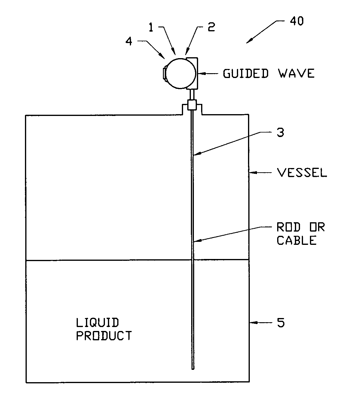
[0014]The invention is a method of detecting and the presence of an unexpectedly weak reflected signal from a liquid / liquid interface, using a basic guided wave device as the level measurement device. The basic guided wave device 40 is shown in FIG. 1 disposed in a tank 5, although this system may also be deployed in an external chamber fluidly connected to the tank (not shown). The basic guided wave device includes a signal generator / emitter 1 and a signal receiver 2 (the emitter and receiver may be integrated into a single unit as depicted in FIG. 1) and a waveguide 3 operationally connected to the emitter 1 and receiver 2. The waveguide 3 may be constructed from flexible cable(s), or solid rod(s) or coaxial probe or other suitable construction known in the art. The waveguide may be positioned in the interior of the tank or storage chamber, or in a stilling well, displacer or an external chamber (all such being fluidly connected to the interior of the tank or storage chamber). The...


PUM


Abstract

The invention is a method to detect a weak interface signal in a guided wave level measurement device. The device includes a waveguide, a signal generator and a signal receiver, the signal generator and signal receiver being operationally connected to the waveguide. The method includes the steps of transmitting an outgoing signal; monitoring the signal received at the signal receiver to detect a first signal level that exceeds or equals a first threshold level (TH1) and if such a signal level is detected, continue monitoring the received signal to detect a second signal level that exceeds or equals TH1. Finally, if a second signal level in excess of TH1 is detected, continue monitoring the received signal to detect a third signal level that exceeds or equals a second threshold level TH2.

Description

FIELD OF THE INVENTION[0001]The present invention relates to a system and method for monitoring fluid levels in containers, such as storage tanks, and more particularly, where more than one fluid is present in the tank, creating a fluid / fluid interface.BACKGROUND OF THE INVENTION[0002]Various devices have been conventionally employed to measure the level of a fluid or the interface levels between two mediums (such as oil / water). Generally, these devices consist of a sensor within a container, and means for sending data from the sensor to a location where it would be detected and converted into a usable format representative of the level of fluid within the container. One common device is a time domain reflectometry device having a waveguide positioned in the tank (or a side chamber) and a signal generator and signal receiver. The device generates an electromagnetic signal which propagates down the waveguide. Upon reaching a fluid interface of fluids having differing dielectric const...

Claims


Application Information

Patent Timeline
IPC IPC(8): G01F19/00
CPCG01F23/284
Inventor FAUVEAU, ERIC
Owner ABB INC
Learn More