
Developing device and image forming apparatus provided with same

a technology of developing device and image forming apparatus, which is applied in the direction of electrographic process apparatus, instruments, optics, etc., can solve the problems of inability to carry on the end portions of the toner supporting member the developer's amount and inability to carry on the developer's amount, so as to achieve the effect of appropriately preventing toner scattering

Active Publication Date: 2008-02-19
SHARP KK
View PDF7 Cites 7 Cited by
  • Summary
  • Abstract
  • Description
  • Claims
  • Application Information

AI Technical Summary

Benefits of technology

[0013]The present invention was made in view of the aforementioned conventional problems. An object of the present invention is to provide a developing device for use in a two-component developer, in which toner scattering can be appropriately prevented, and an image forming apparatus provided with the same developing device.
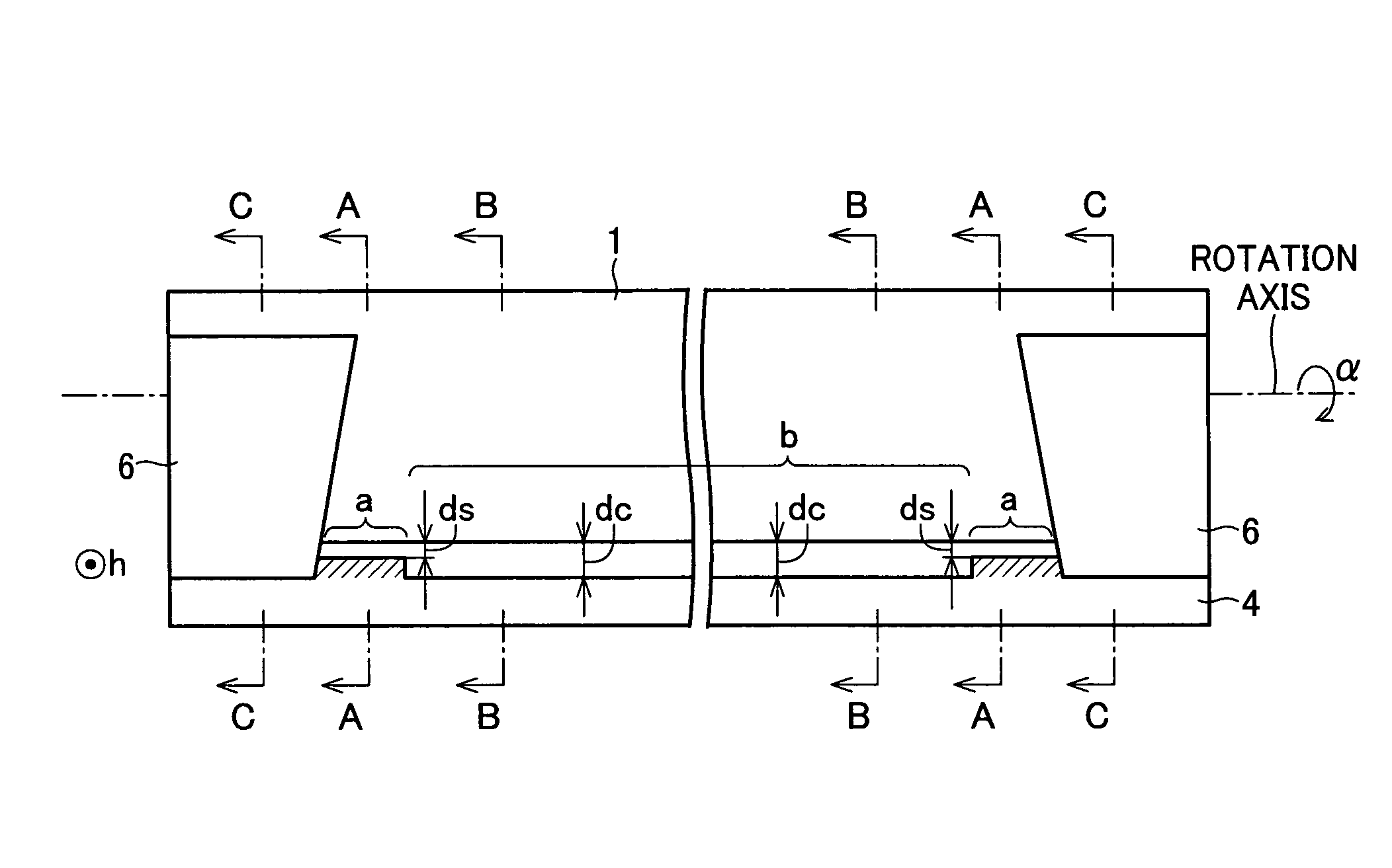
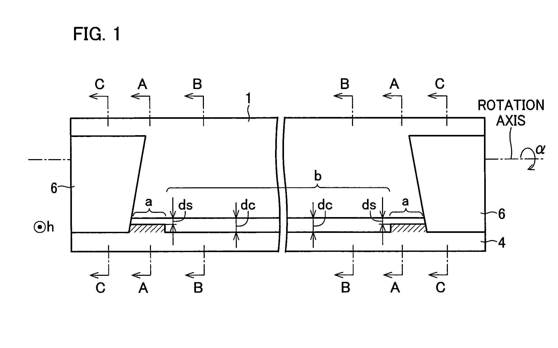
[0015]With this arrangement, in which the end gaps are narrow, it is possible to utilize the toner itself to prevent the developer from scattering out of the developer tank through either of the end gaps. At the end portions of the toner supporting member, there is instability in the amount of the developer carried on the end portions of the toner supporting member and in the amount of the electrification of the developer. Because of such a problem, the scattering of the developer is easy to occur in the end portions of the toner supporting member. The above arrangement, in which the gaps at the end portions are narrow, however, prevents the scattering of the developer in the end portions of the toner supporting member by preventing an air flow at the end portion by utilizing the developer itself to seal the gap.
[0016]Furthermore, the center gap is wider than the end gaps in the above arrangement. This attains lower resistance for the flow at the center portion. As a result, the internal pressure, emitting air, or the flow rate of the toner can be kept low in the center portion. Therefore, this arrangement is effective to prevent the scattering of the developer, even for a case where process speed is fast.
[0017]An image forming apparatus according to the present invention is provided with the developing device. Therefore, the scatting of the developer is appropriately prevented in the image forming apparatus for use of the two-component developer.

Problems solved by technology

At the end portions of the toner supporting member, there is instability in the amount of the developer carried on the end portions of the toner supporting member and in the amount of the electrification of the developer.

Method used


Image

  • Developing device and image forming apparatus provided with same
  • Developing device and image forming apparatus provided with same
  • Developing device and image forming apparatus provided with same

Examples


Embodiment Construction

[0023]One embodiment of the present invention is described below referring to drawings.

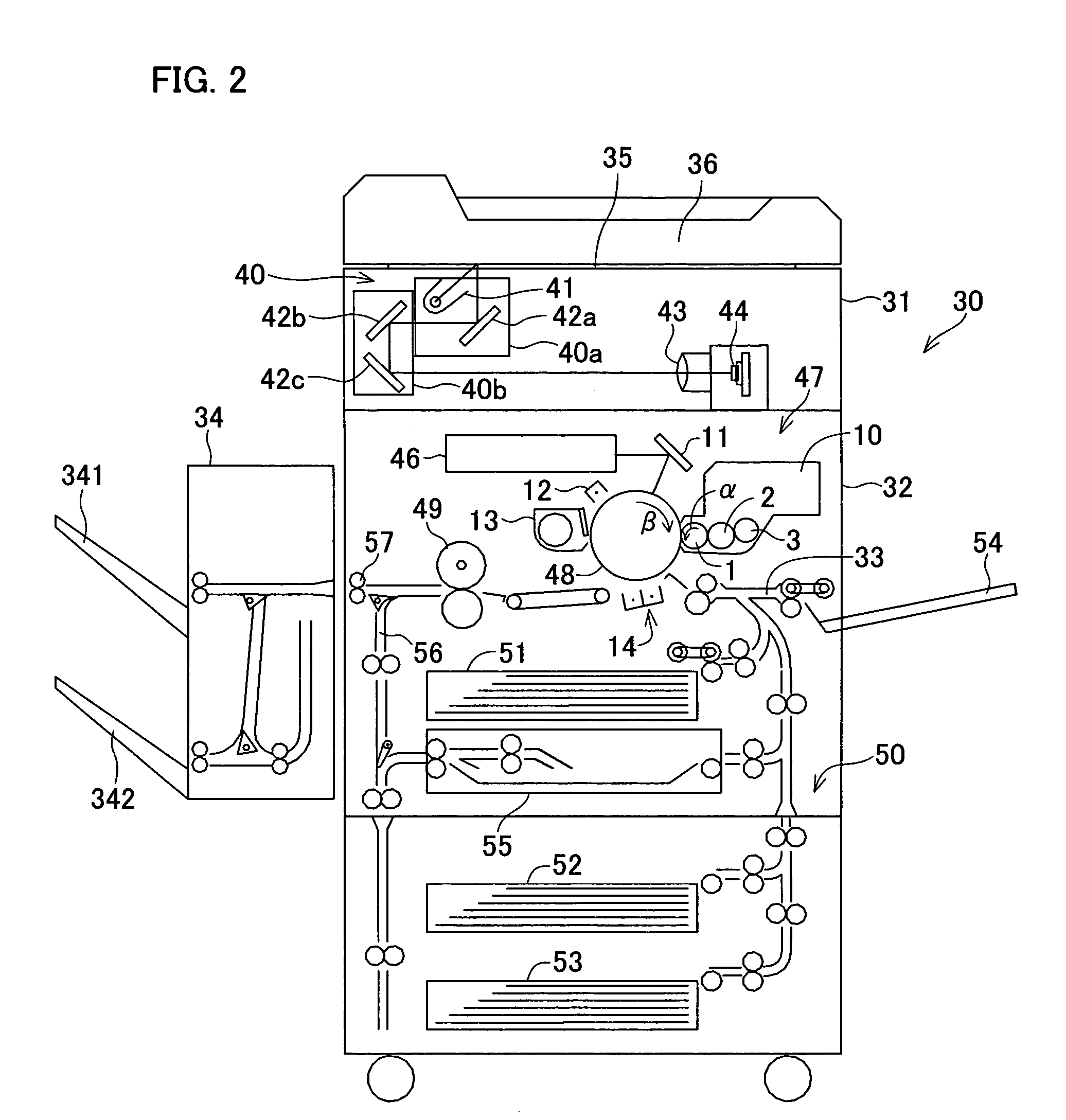
[0024]As illustrated in FIG. 2, a developing device 10 according to the present embodiment is provided to a copying machine (image forming apparatus) 30. The copying machine 30 functions as a copying machine, printer, and faxing machine, and is provided with a scanner section 31 and a laser printer section (laser recording section) 32. Moreover, the copying machine 30 has a process speed (transport speed for sheet (recording material, recording medium)) of 100 mm / sec or higher, which enables the copying machine 30 to perform high-speed image formation.

[0025]The scanner section 31 includes a document platform 35, an RADF (Recirculating Automatic Document Feeder) 36, and a scanner unit 40. The document platform 35 is made of transparent glass. The RADF 36 is for automatically supplying a document(s) onto the document platform 35. The scanner unit 40 is a document image reading unit for scanning an i...


PUM


Abstract

A developing device is arranged such that Dg<ds<3Dg, and 3Dg<dc<6Dg, where ds is an end gap, Dg is an upstream gap, and dc is a center gap. The gap ds is a gap between a developer tank 4 and either end portion of a developing roller 1 in the downstream of a transportation direction of the developing roller 1. The end portion of the developing roller 1 is an end portion thereof with respect to a rotation direction of the developing roller 1. The gap Dg is a gap between the developing roller 1 and a doctor blade. The gap dc is a smallest gap between the developer tank 4 and the center portion b of the developing roller 1. With this arrangement, it is possible to prevent the toner scattering appropriately in the developing device for use of a two-component developer containing toner and carrier.

Description

[0001]This Nonprovisional application claims priority under 35 U.S.C. § 119(a) on Patent Application No. 2004 / 302214 filed in Japan on Oct. 15, 2004, the entire contents of which are hereby incorporated by reference.FIELD OF THE INVENTION[0002]The present invention relates to a developing device which uses a two-component developer, and an image forming apparatus provided with the developing device.BACKGROUND OF THE INVENTION[0003]Conventionally, an electronic photographic image forming apparatus (printing device) such as a copying device, printer, fax machine or the like, is provided with a photosensitive drum, charging device, exposing device, developing device, transfer device, fixing device, and the like.[0004]In such an image forming apparatus, an electrostatic latent image is formed on a photosensitive surface (electrostatic latent image surface) of the photosensitive drum by electrifying the photosensitive surface by the charging device and then exposing the photosensitive su...

Claims


Application Information

Patent Timeline
Patent Type & Authority Patents(United States)
IPC IPC(8): G03G15/08
CPCG03G15/0817G03G15/0942G03G2215/0609
Inventor NAGATA, TSUTOMUKIMURA, TAKAHIKO
Owner SHARP KK
Learn More