Digital video decoding, buffering and frame-rate converting method and apparatus

Inactive Publication Date: 2008-02-19
SONY CORP +1
View PDF20 Cites 86 Cited by
  • Summary
  • Abstract
  • Description
  • Claims
  • Application Information

AI Technical Summary

Benefits of technology

[0032]A primary objective of the present invention is to provide a video decoding system and method by which video programs can be efficiently and effectively converted from one frame display rate to another. It is a particular objective of the present invention to provide a video decoding system and method by which such frame display rate conversion can be made by repeating the display of fields from received pictures to display a greater number of fields in a given presentation time interval than the number of frames in the interval that are received in the original program.
[0033]A particular objective of the present invention is to provide an efficient and effective system and method for performing frame rate conversions such as, for example, 3:2 pull-down conversions including pull down in VCD and DVD and NTSC-PAL or PAL-NTSC conversions. More particular objectives of the invention include providing for such 3:2 pull-down while facilitating the use of commands such as pause, fast-forward, slow forward, reverse play and other such commands which are often referred to as “trick play” commands. Such objectives also include implementing frame skipping required in audio-visual synchronization.
[0035]A further objective of the present invention is efficient and effective use of buffer memory and to facilitate the use of minimally sized buffer memory to buffer decoded video picture sequences for display during regular play, where frame rate conversions are required for program viewing, and during trick play modes and transitions into and out of trick play modes, particularly while maintaining optimal display quality. An additional objective of the invention is to provide a memory management system operative to map decoded pictures to buffer memory and allocate buffer memory so as to allow for the sharing of memory locations by more than one field in a way that reduces memory requirements.
[0036]According to the preferred embodiment of the present invention, an MPEG video decoder is provided with a decompression and transformation section which decodes a full frame of video on command by a single method that applies regardless of buffer memory and frame rate conversion considerations that would otherwise call for differing display sequences of the decoded pictures. The decoder is provided with a display control module that handles all frame rate and field sequence issues in response to host configuration information, particularly buffer memory size and system type (NTSC or PAL), and to host command signals, such as trick play commands, as well as to information in the received bitstream, particularly the sequence and picture headers and extensions. The display control module handles these issues, in a way that allows the other components of the decoder and of the display output logic to operate in a simple and consistent manner.
[0038]In the certain preferred embodiments, default attributes are predicted based on frame rate conversion considerations and then modified to give consideration to field display sequence information accompanying the pictures of the program. The generation of attribute tables considers buffer memory size, and field display order is modified to the extent necessary to allow the program to be reproduced at a proper display rate even when memory is small, using opposite field data where necessary. The field sequence order facilitates the use of output buffers for B-frame data that is in the range of from 0.53 to 0.67 frames in size.
[0040]The invention provides versatility for various temporal up-sampling and down sampling schemes, particularly frame rate conversion schemes, and its operation is particularly smooth. The invention supports the use of less than three full frames of buffer memory, particularly that referred to as 2.53 mode or 2.53 frame DRAM memory configuration, as well as three frame and four or more frame video buffer memory. The invention also supports various trick play modes and their use simultaneously with 3:2 pull-down. The system and method provide versatile conversion and the ability to handle conversions between PAL and NTSC, with and without 3:2 pull-down, in both VCD and DVD as well as other formats.

Problems solved by technology

This increases the decoder speed requirements, the required buffer memory, or both, affecting the cost and complexity of the receiver.
An additional problem presented by the variety of conversion requirements is the complexity of the video decoding needed to deal with the alternative conversion situations using methods of the prior art.
Furthermore, not all video presentation systems are to be used in applications requiring the high resolution and other capabilities of DVD or other MPEG compliant systems.
Since it is not economical to produce electronic circuits in small quantities for each application, prior art systems typically are not produced to economically serve each of the applications for which they are needed.
For all of these purposes, the need to make frame rate conversions has the propensity to increase the complexity and cost of the video decoding system or the size and cost of the video buffer memory.

Method used


Image

  • Digital video decoding, buffering and frame-rate converting method and apparatus
  • Digital video decoding, buffering and frame-rate converting method and apparatus
  • Digital video decoding, buffering and frame-rate converting method and apparatus

Examples


example 1

[0089]The case where no frame rate conversion is required and a 3-frame video buffer is available includes the situation where pictures in the program have a display rate that is the same as that of the display 34, as, for example, a program of 30 frames per second being presented by a system having an NTSC display format. The output sequence of the fields of the successive frames of the picture, which are identified by the superscripts 1, 2, . . . etc., is either:

T1B1,T2B2,T3B3, . . . , etc.

or

B1T1,B2T2,B3T3, . . . ,etc.,

depending on which field of a frame is to displayed first. The solution is straightforward.

example 2

[0090]The case where 3:2 conversion is required with a 3-frame video buffer available includes the situation where, for example, a motion picture is encoded in progressive frames at 24 frames per second to be presented by a system having an NTSC display format of 30 frames (60 fields) per second. This requires a 4:5 frame rate conversion. In this case, every four frames of a program bitstream in the form of:

T1B1,T2B2,T3B3,T4B4

must be output as five frames. MPEG specifies that such conversion involve outputting the first field of the first frame twice as the first and third fields and outputting the second field of the third frame as the sixth and eighth fields of a ten field sequence. Fields of any given frame are output in the order TB, BT, TBT or BTB. For 4:5 frame rate conversion, the output sequence of the fields of the successive frames 1, 2, . . . etc. of the picture is:

T1B1,T1B2,T2B3,T3B3,T4B4

A similar result can be achieved with the sequence:

B1T1,B1T2,B2T3,B3T3,B4T4

[0091]...

example 3

[0104]The case where 3:2 pull-down conversion is required with a 3-frame video buffer available in the case of, for example, a motion picture is encoded in progressive frames at 20 frames per second to be presented by a system having an NTSC display format of 30 frames (60 fields) per second. This requires a 2:3 frame rate conversion. In this case, every two frames of a program bitstream in the form of:

T1B1,T2B2

must be output as three frames. Such conversion may involve outputting the first field of the first frame twice as the first and third fields and outputting the second field of the second frame twice as the fourth and sixth fields of a six field sequence. The output sequence of the fields of the successive frames 1, 2, . . . etc. of the picture is:

T1B1,T1B2,T2B2

A similar result can be achieved with the sequence:

B1T1,B1T2,B2T2

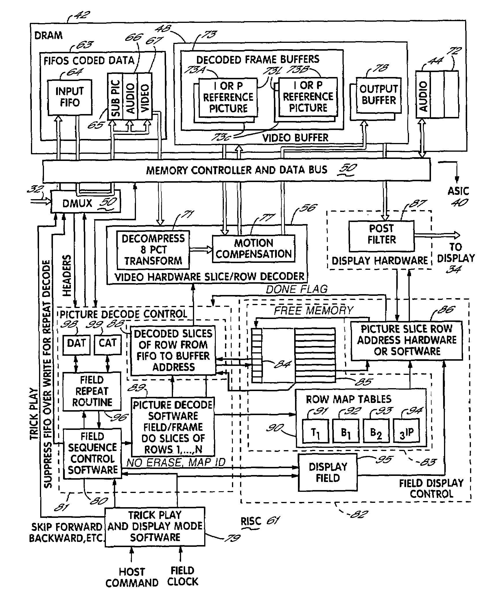
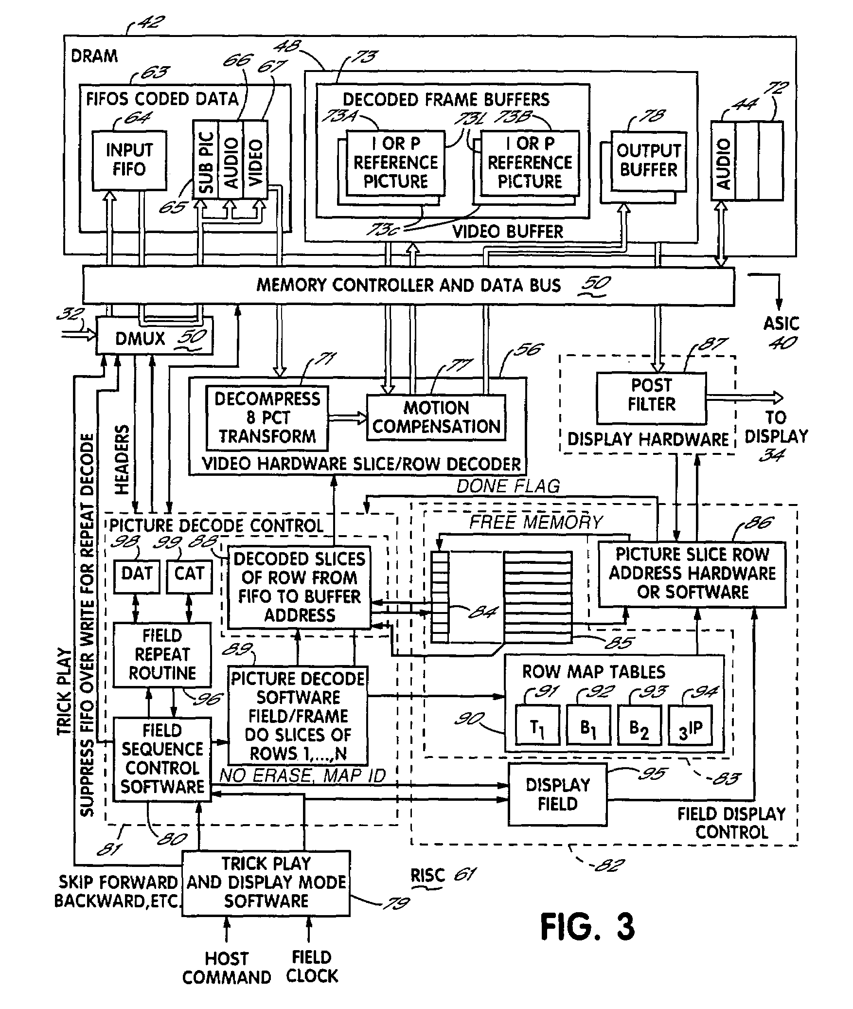
[0105]To output the sequence T1B1,T1B2,T2B2, the display sequence control 80 controls the decoding and output as follows:

[0106]Start with decoding of ...


PUM


Abstract

A decoder decodes full frame MPEG-2 video by a single method that applies regardless of buffer memory and frame rate conversion considerations. A display control module handles frame rate and field sequence in response to host configuration, trick play command signals, and information in the received bitstream. Pictures are decoded as buffer memory for the decoded pictures becomes available, and picture display attributes are assigned and stored in a table, one string for each decoded picture. Frame rate and field sequence are managed in light of memory constraints, to produce a high quality result without re-decoding data.

Description

[0001]This application is a divisional of Ser. No. 09 / 281,013, filed Mar. 30, 1999 now U.S. Pat. No. 6,658,056, which is related to the following commonly assigned U.S. patent applications, each of which is hereby expressly incorporated by reference herein:[0002]Ser. No. 08 / 846,590, filed Apr. 30, 1997, by Edward J. Paluch, entitled Memory Address Generation For Digital Video, now abandoned;[0003]Ser. No. 08 / 865,749, filed May 30, 1997, by Bublil et al., entitled Special Purpose Processor For Digital Audio / Video Decoding, now U.S. Pat. No. 6,012,137;[0004]Ser. No. 08 / 866,419, filed May 30, 1997, by Ozcelik et al., entitled Task And Stack Manager For Digital Video Decoding, now U.S. Pat. No. 5,928,321;[0005]Ser. No. 09 / 001,122, filed Dec. 30, 1997, by Bose et al. entitled Motion Compensated Digital Video Decoding and Buffer Memory addressing Therefor, now U.S. Pat. No. 6,215,822;[0006]Ser. No. 09 / 001,129, filed Dec. 30, 1997, by Bose et al. entitled Motion Compensated Digital Video D...

Claims


Application Information

Patent Timeline
IPC IPC(8): H04N7/12G06K9/36G06T9/00H04N7/01H04N7/26H04N7/50
CPCH04N7/01H04N19/176H04N19/102H04N19/61H04N19/152H04N19/85H04N19/44H04N19/42H04N19/423H04N19/427H04N19/174
Inventor DURUOZ, CEM I.OZCELIK, TANERSHIMIZU, YOSHINORI
Owner SONY CORP
Why Eureka
Try Eureka