Dual-circuit steer-by-wire steering system comprising a common cradle

Inactive Publication Date: 2008-02-19
THYSSENKRUPP PRESTA STEERTEC
View PDF15 Cites 6 Cited by
  • Summary
  • Abstract
  • Description
  • Claims
  • Application Information

AI Technical Summary

Benefits of technology

[0007]If more than one guide rod is present, these are preferably arranged parallel to each other at the same height. However, it is also possible that the guide rods are arranged one above the other and parallel to each other. The point of application of force of the steering tie rods on the cradle(s), which is / are displaceably mounted on the guide rods, is to be selected as a function of the given installation space. Advantageously, the points of application of force of the steering tie rods of both guided wheels are to be selected in such a way that they lie centrally between two parallel guide rods, so that no torque acts upon the guide rods. As a result of this central application of force it is in particular possible to provide long guide rods, which advantageously leads to minimum steering error when the springs are compressed and released. One or more long guide rods can also be used, whereby in addition a central steering tie rod links the two points of application of force of the two steering tie rods with one another. This central steering tie rod is to be arranged parallel to the guide rod(s). Advantageously, it is displaceably mounted on the bodywork parallel to the guide rod(s), whereby advantageously no flexural stress acts upon the steering tie rods.
[0009]Because the guide rods themselves form the line for the fluid medium, advantageously no additional connecting hoses are necessary as in the case of conventional steering systems, so that advantageously less risk of leakage results.
[0011]As already stated, if the above-described steer-by-wire steering system is used in this way, the control valves fitted in the steering circuits can be valves having open or closed center. The use of valves having closed center with simultaneous use of an accumulator has the advantage that the pump does not have to be in continuous operation in order to build up a working pressure of the fluid medium, whereby advantageously energy and thus fuel are saved.

Problems solved by technology

However it is also possible that a minimum of one guide rod is provided, which only fulfills the cradle-guiding function, but does not form a piston-cylinder system.

Method used


Image

  • Dual-circuit steer-by-wire steering system comprising a common cradle
  • Dual-circuit steer-by-wire steering system comprising a common cradle
  • Dual-circuit steer-by-wire steering system comprising a common cradle

Examples


Embodiment Construction

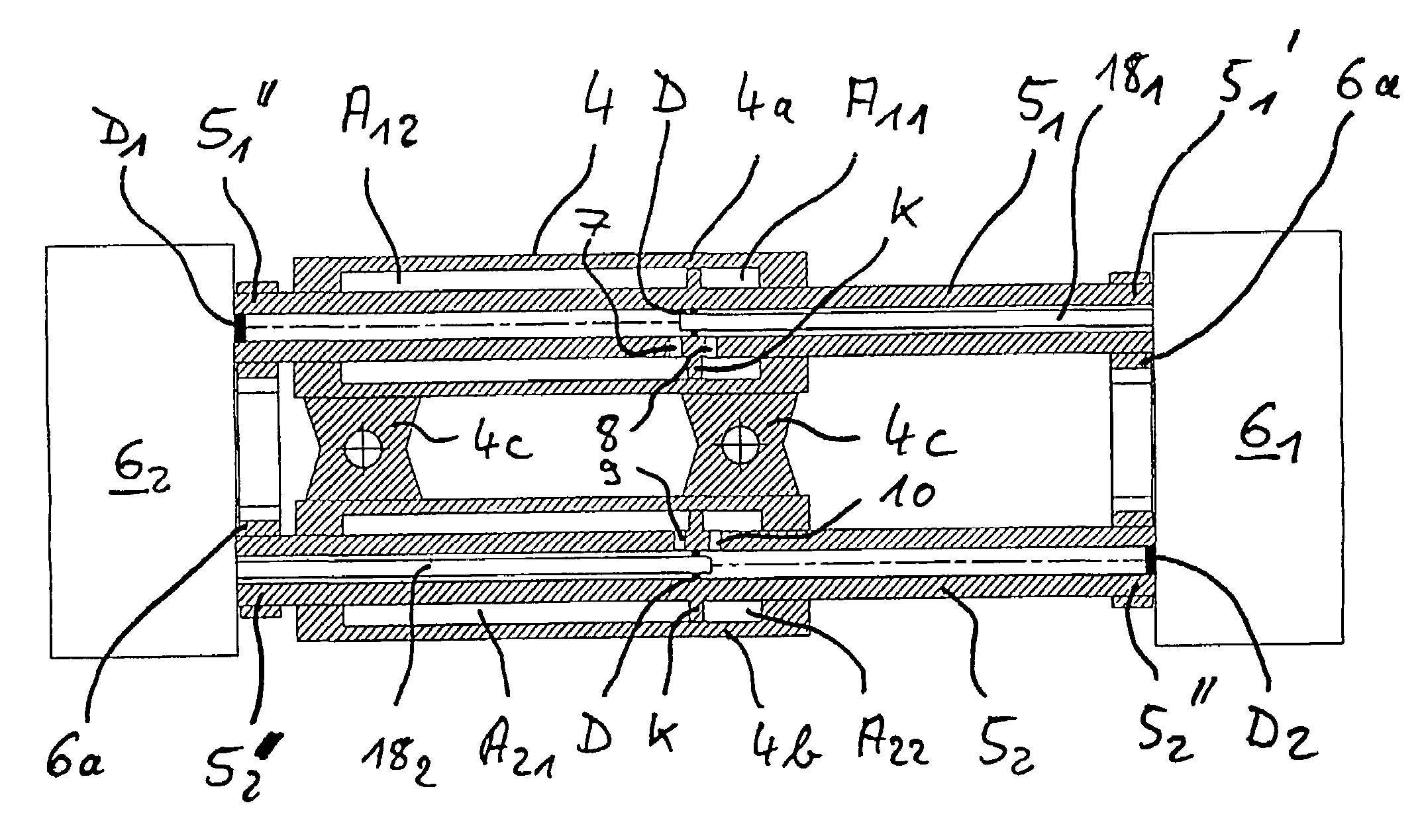
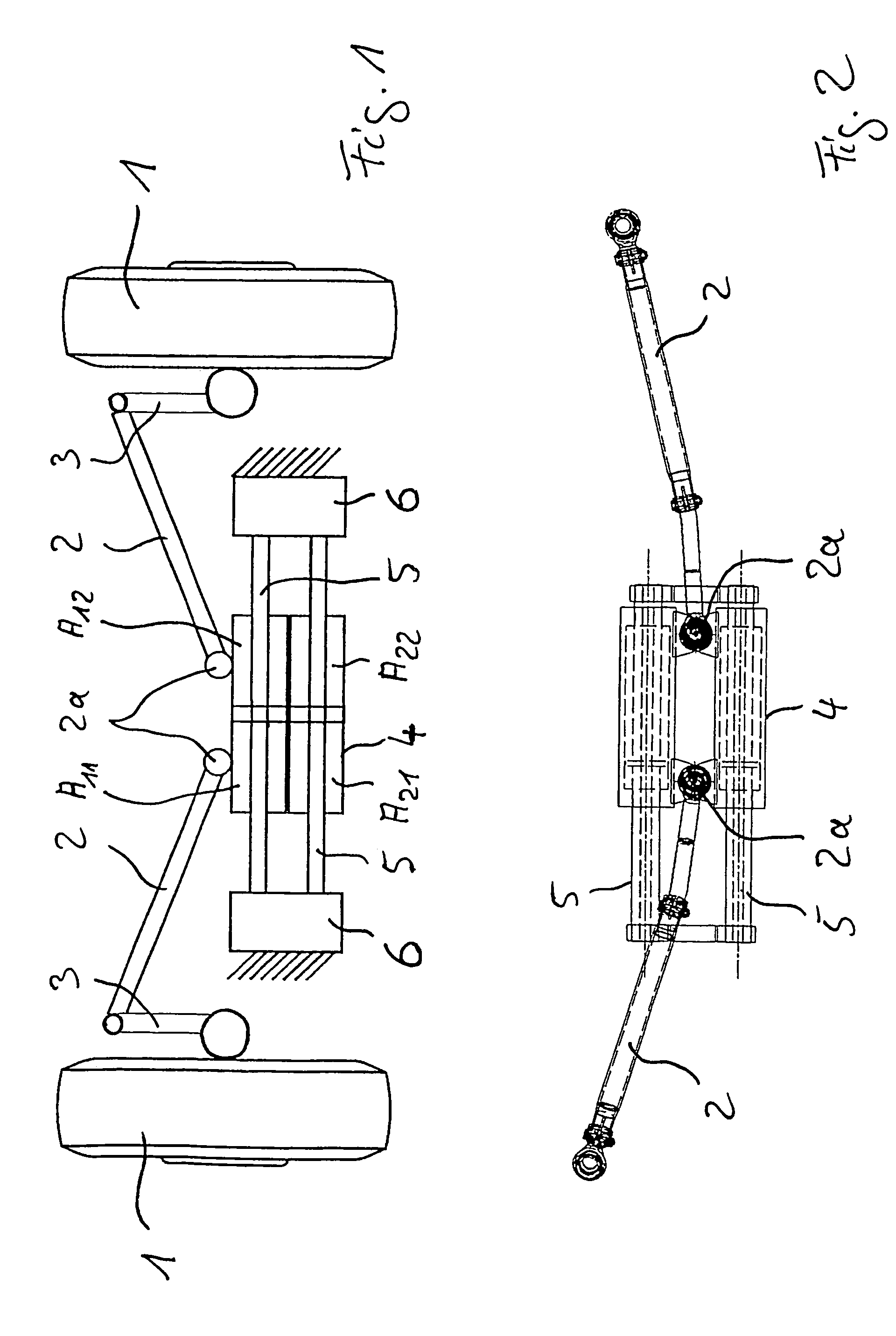
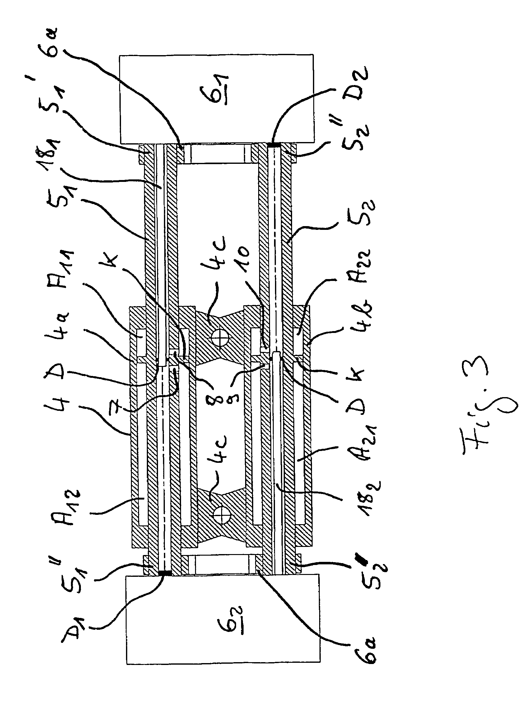
[0021]FIG. 1 shows a schematic illustration of a first embodiment of the steer-by-wire steering system in accordance with the invention, whereby a cradle 4, which is movably and / or displaceably mounted on two guide rods 5, adjusts steerable wheels 1 by means of steering arms 3 and steering tie rods 2. The cradle 4 together with the guide rods 5 forms four working chambers A11, A12, A21, and A22. The guide rods 5 are rigidly mounted on the bodywork or chassis of the vehicle between two valve blocks 6. The cradle 4 and the guide rods 5 form a special piston-cylinder system in which the kinetics are reversed, since here the piston and / or the guide rod(s) are static and the cylinder and / or cradle moves.

[0022]FIG. 2 shows a further embodiment of the steer-by-wire steering system in accordance with the invention, in which the points of application of force 2a of the steering tie rods 2 are arranged on the cradle 4 centrally between the two guide rods 5. As a result of the central arrangem...


PUM


Abstract

The invention relates to a steer-by-wire steering system comprising a hydraulic control unit that acts on the steerable wheels (1, 20), the control unit having at least one cradle (4, 23), which is displaceably mounted on at least one guide rod (5, 24) that passes through the respective cradle (4, 23). The respective cradle (4, 23) and the corresponding guide rod(s) (5, 24) form working chambers (A11, A12, A21, A22) of a piston-cylinder system, whereby each respective guide rod (5, 24) has at least one channel (KA11, KA12, KA21, KA22), each terminating in the vicinity of a working chamber (A11, A12, A21, A22). The cradle or cradles (4, 23) adjust the steerable wheels (1, 20) directly or by means of steering tie rods (2, 21).

Description

BACKGROUND OF THE INVENTION[0001]The present invention relates to a steer-by-wire steering system, comprising a hydraulic control unit that acts on the steerable wheels.[0002]The control units of generic dual-circuit steer-by-wire steering systems normally consist of two control cylinders, which are individually mounted on their own and which need flexible feed lines to supply the fluid medium. Due to their structure the control cylinders are normally bulky and prone to fault on account of the flexible feed lines.[0003]Object of the present invention is to create a steer-by-wire steering system, the structure of which is as compact and as non-prone to fault as possible.SUMMARY OF THE INVENTION[0004]This object is achieved according to the invention with a steer-by-wire steering system wherein the control unit has at least one cradle, which is adapted to adjust the steerable wheels directly or via tie rods, wherein the at least one cradle is displaceably mounted on at least one guide...

Claims


Application Information

Patent Timeline
IPC IPC(8): B62D5/06B62D5/10B62D5/12F15B15/14F15B18/00
CPCB62D5/12F15B15/1457F15B15/149F15B18/00
Inventor SIKORA, KARSTENHORWATH, JOCHEN
Owner THYSSENKRUPP PRESTA STEERTEC
Why Eureka
Try Eureka