
Image enhancement or correction software, method, apparatus and system for substantially minimizing blur in the scanned image

a technology of image enhancement and correction technique, applied in image enhancement, instruments, applications, etc., can solve the problems of blur in the image or the smeared image being caused by the limit in spatial resolution, unreliable information including the occlusion rate, and the general experience of ct scanner systems a certain amount of blur, etc., to achieve the effect of minimizing the blur in the image data

Inactive Publication Date: 2008-02-12
TOSHIBA MEDICAL SYST CORP
View PDF13 Cites 6 Cited by
  • Summary
  • Abstract
  • Description
  • Claims
  • Application Information

AI Technical Summary

Benefits of technology

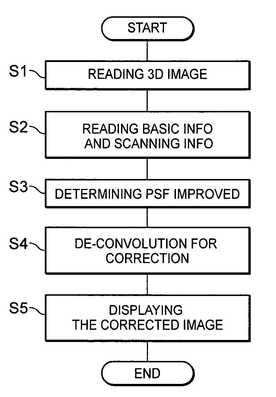
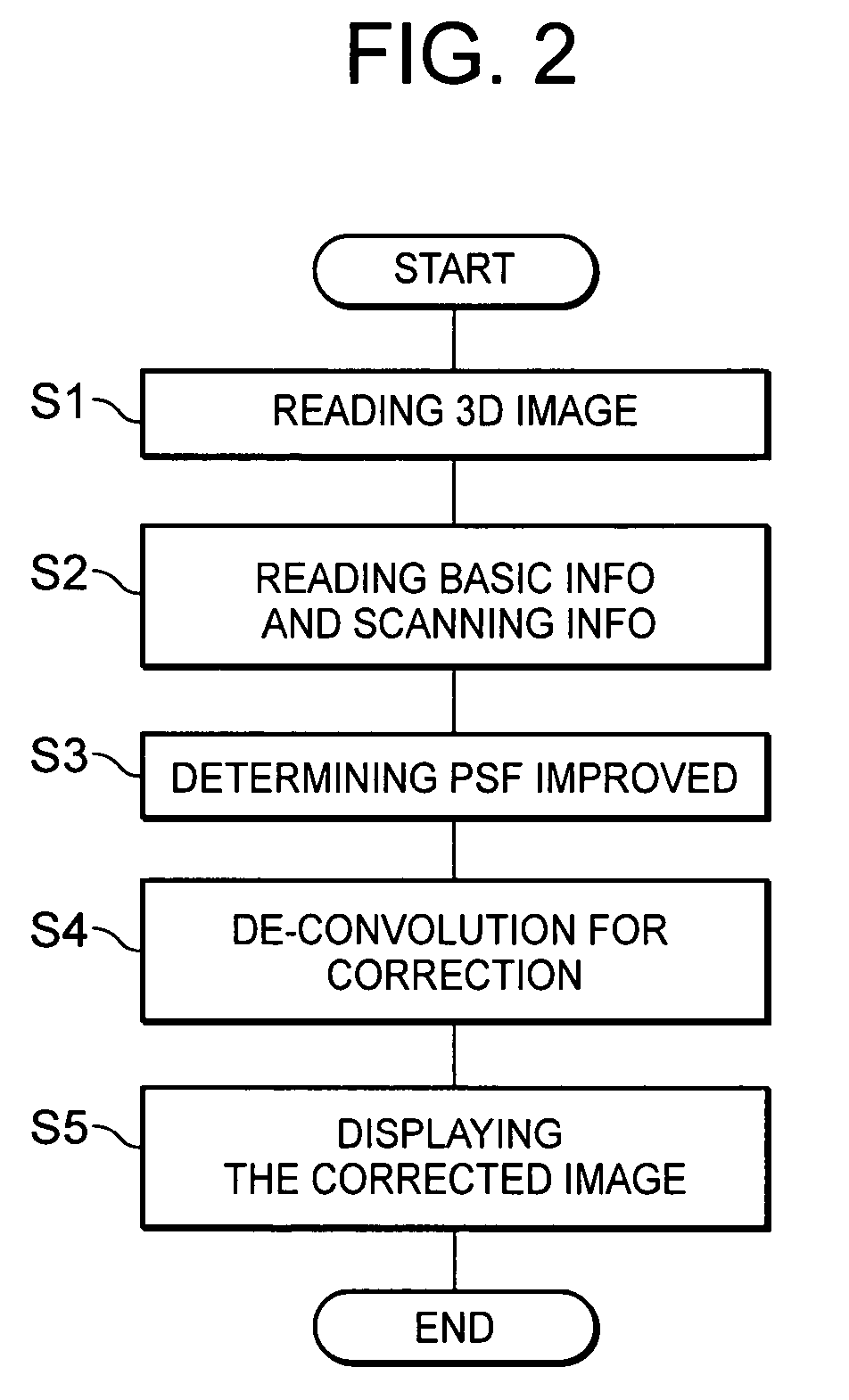
[0008]In order to solve the above and other problems, according to a first aspect of the current invention, a method of substantially minimizing blur in image data, including the steps of: determining a point spread function (PSF) based upon the first image data by scanning a known object; scanning an object of interest to generate second image data with X-ray CT scanning parameters; obtaining an improved PSF based on a combination of scanning parameters and the PFS, the scanning parameters including at least one of slice thickness of detector collimation, slice thickness for reconstruction, type of convolution filter, type of reconstruction mode, pixel size, helical pitch and focus size; and de-convoluting the second image data with the improved PSF.
[0009]According to a second aspect of the current invention, a method of substantially minimizing blur in image data, including the steps of: determining a point spread function (PSF) based upon the first three-dimensional image data by scanning a known object; scanning an object of interest to generate second three-dimensional image data with X-ray CT scanning parameters; obtaining an improved PSF based on a combination of parameters and the PFS, the parameters including a combination of device-dependent parameters and scanning condition parameters to generate the improved PSF, the scanning parameters including at least one of slice thickness of detector collimation, slice thickness for reconstruction, type of convolution filter, type of reconstruction mode, pixel size, helical pitch and focus size; and de-convoluting the second three-dimensional image data with the improved PSF.
[0010]According to a third aspect of the current invention, a method of substantially minimizing blur in image data, including the steps of: scanning a known object to generate first image data; determining a point spread function (PSF) based upon the first image data for the known object; scanning an object of interest to generate second image data; weighing the PSF according to a combination of parameters to generate an improved PSF, the parameters including a combination of device-dependent parameters and scanning condition parameters, a value of each of the parameters being ultimately associated with a predetermined weight value, the device dependent parameters including dfocus-x for indicating a focus size in the x-direction dfocus-z for indicating a focus size in the Z-direction, adet-x for indicating a detector aperture in the x-direction and dfocus to enter for indicating a distance between a focus and a rotation center; and de-convoluting the second image data with the improved PSF.

Problems solved by technology

For the measurements or display of certain minute structures, the CT scanner systems generally experience a certain amount of blur, smear or inaccuracy in the three-dimensional image data.
The blur in the image or the smeared-out image is caused by the limit in spatial resolution.
Ultimately, the inaccurate measurements of certain structures such as the thickness of blood vessel walls lead to unreliable information including the occlusion rate.
As the result of the differing spatial resolutions, the image quality is not stable.

Method used


Image

  • Image enhancement or correction software, method, apparatus and system for substantially minimizing blur in the scanned image
  • Image enhancement or correction software, method, apparatus and system for substantially minimizing blur in the scanned image
  • Image enhancement or correction software, method, apparatus and system for substantially minimizing blur in the scanned image

Examples


Embodiment Construction

)

[0019]Based upon incorporation by external reference, the current application incorporates all disclosures in the corresponding foreign priority document (JP 2003-205025 filed Jul. 31, 2003) from which the current application claims priority.

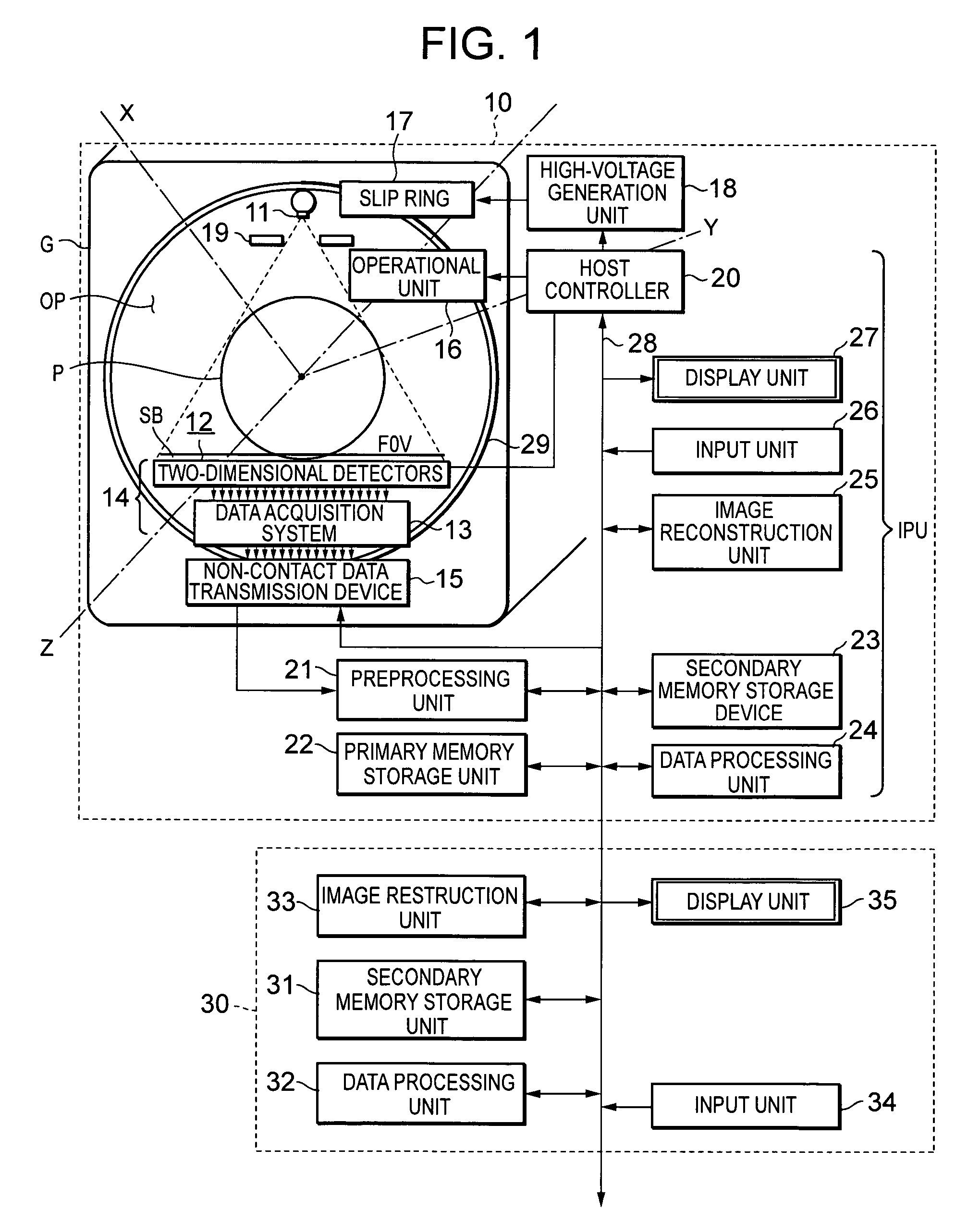
[0020]Referring now to the drawings, wherein like reference numerals designate corresponding structures throughout the views, and referring in particular to FIG. 1, a block diagram illustrates one preferred embodiment of a multi-slice CT scanner device 10 and an external image processing device or console 30 according to the current invention. The multi-slice CT device 10 generally includes a donut-shaped gantry G in which a known object or a subject such as a patient P is scanned by an X-ray. The multi-scan CT device 10 also includes a data processing unit IPU where the scanned data is processed. The gantry G further includes a slip ring 17, a rotational ring portion 21, a gantry operational unit 16, an X-ray tube 11 and an X-ray detection sys...


PUM


Abstract

Three-dimensionally reconstructed images are not ideal due to blur or smear that is caused by various sources in an X-ray CT scanner. In order to substantially minimize the blur in the three-dimensionally reconstructed image, a known PSF is weighed according to a combination of predetermined parameters. The parameters include two types of information. One group of the parameters is related to device characteristics of the scanner device while the other is related to the scanning conditions of a particular scan. The improvement is performed in any combination of the X, Y and Z directions. The improved PSF's are used to de-convolute the three-dimensionally reconstructed CT image. As a result, the blur and smear are substantially removed from the three-dimensionally reconstructed image data for good visualization as well as accurate physical measurements in the scanned image. The improved techniques according to the current invention are applicable to two-dimensional image data.

Description

FIELD OF THE INVENTION[0001]The current invention is generally related to an image enhancement or correction technique for improving image resolution, and more particularly related to the image enhancement or correction software, method, apparatus and system for substantially minimizing blur or smear in the three-dimensionally reconstructed scan image data from an X-ray computer assisted tomography or computerized tomography (CT) scanner.BACKGROUND OF THE INVENTION[0002]In recent years, X-ray CT scanners have made significant improvement and have been widely used for computerized tomography. The use of the scanner is not only in the medical field, but also in other fields including industrial applications. The X-ray CT scanners have also made rapid advancements. For example, in response to the demands from the medical community for high resolution and wide scanning range, multi-slice X-ray CT scanners have been developed for wide use. The multi-slice X-ray CT scanner generally inclu...

Claims


Application Information

Patent Timeline
Patent Type & Authority Patents(United States)
IPC IPC(8): G06K9/62G06K9/00A61B5/055A61B6/03A61B8/14G06K9/40G06T1/00G06T5/00G06T5/50
CPCG06T5/003G06T5/50G06T2200/04G06T2207/10081G06T2207/30101
Inventor RIFU, TOSHIHIRO
Owner TOSHIBA MEDICAL SYST CORP
Learn More