
Pressure gauge for organic materials

a pressure gauge and organic material technology, applied in the direction of resistance/reactance/impedence, instruments, measurement devices, etc., can solve the problems of accumulated film thickness information loss, affecting the accuracy of the pressure gauge, so as to reduce the risk of organic material degradation and achieve effective sensitivity

Active Publication Date: 2008-01-29
GLOBAL OLED TECH
View PDF6 Cites 41 Cited by
  • Summary
  • Abstract
  • Description
  • Claims
  • Application Information

AI Technical Summary

Benefits of technology

[0011]It is an advantage of this invention that it can measure the pressure, and thus the deposition rate, of organic or inorganic materials while significantly reducing the risk of organic material degradation. It is a further advantage of this invention that it can measure the pressure of vaporized organic or inorganic materials with effective sensitivity to the pressure. It is a further advantage of this invention that it can be used to continuously measure the deposition rate over extended periods of operation without loss of sensitivity because no material condenses on the sensor. The pressure sensor can additionally be used as a temperature sensor when the filament is not driven with an external current.

Problems solved by technology

These sensors can provide reliable deposition rate and deposited thickness information when the film deposited on their surface is very thin, adheres well to the surface, and has a high density, but their accuracy diminishes rapidly as the deposited film thickness increases.
This problem is especially troublesome with low-density films such as with organic materials and has necessitated frequent replacement of the vibrating element and disruption of the manufacturing process.
Shutters have also been used to extend the lifetime of a crystal quartz monitor, but no deposition rate information is collected when the shutter is closed, and the accumulated film thickness information is lost.
At high deposition rates, both of these solutions are inadequate since the vaporized material reaches a critical thickness on the monitor in a short period of time.
This has the undesirable effect of decreasing the sensitivity of the pressure sensor at higher pressures.
However, standard Pirani gauges have several difficulties in measuring the pressures necessary to achieve the thin films of organic materials desired in an OLED device.
Standard Pirani gauges are not always sufficiently sensitive to the pressures required for such coatings when the gauge is heated above the condensation temperature of the organic vapor.
For example, the sensing wire in some commercial Pirani gauges are to be run near 1700° C. Temperatures this high are completely unsuitable for measuring organic materials, which will often decompose at this temperature, leading to loss of costly material, as well as carbon deposition onto the incipient device and the coating apparatus.

Method used


Image

  • Pressure gauge for organic materials
  • Pressure gauge for organic materials
  • Pressure gauge for organic materials

Examples


Embodiment Construction

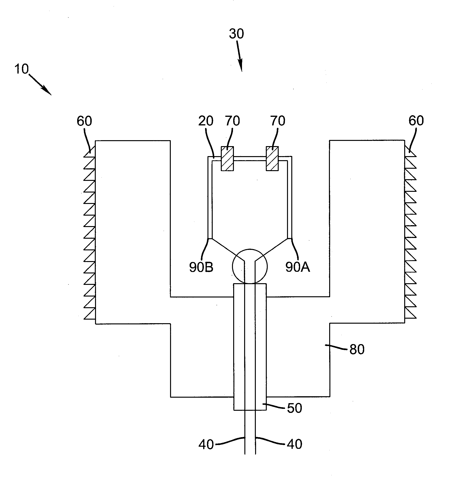
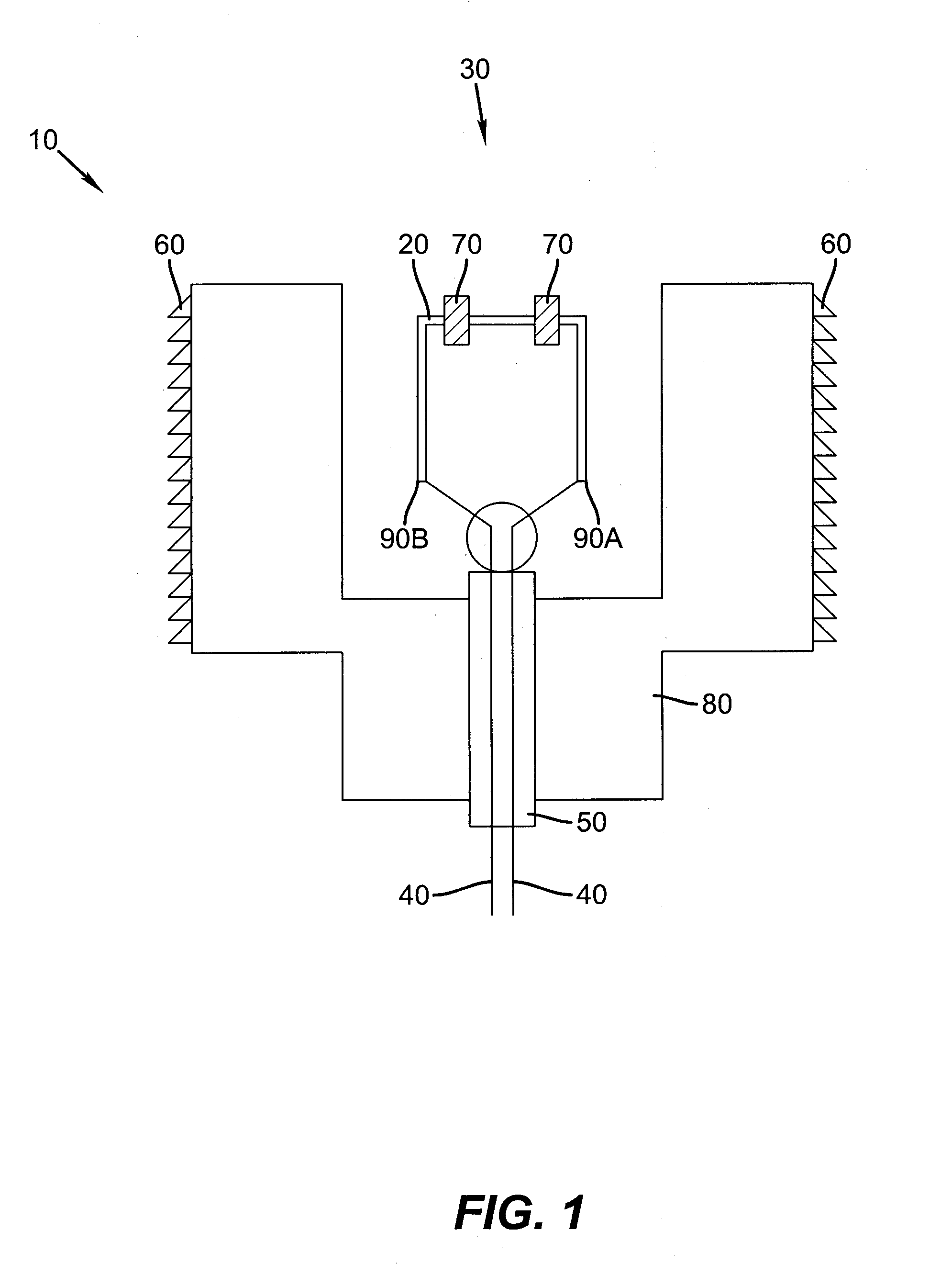
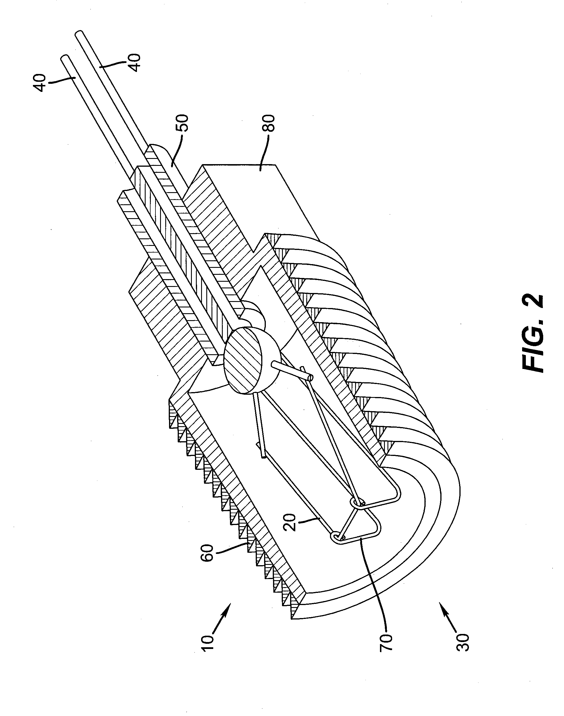
[0021]Turning now to FIG. 1, there is shown a cross-sectional view of one embodiment of one part of a vacuum gauge in accordance with this invention for measuring the pressure of vaporized organic material used in forming a layer of a device. Extended filament unit 10 is part of a vacuum gauge of the Pirani type and is designed to fit into a manifold. The unit includes an extended filament 20 in a dual-helix configuration, which will be described further below. The unit includes a housing 80 with a thread 60 that interfaces with the manifold to create a vacuum-tight seal that also acts to conduct heat from the manifold to the housing so that the manifold and housing are at essentially the same temperature. Opening 30 into the manifold permits the vacuum inside the manifold to contact filament 20 so that the filament is subject to the vaporized material inside the manifold. In one embodiment, the vaporized material inside the manifold is a vaporized organic material. Filament 20 is s...


PUM


Abstract

A vacuum gauge of the Pirani type for measuring the pressure of vaporized organic or inorganic material used in forming a layer of a device, comprising: an extended filament having a thickness of 5 microns or less and having a temperature coefficient of resistance greater than 0.0035 / ° C., the filament being subject to the vaporized organic or inorganic material; means for applying a current to the filament so that the temperature of the filament is less than 650° C. so as not to degrade the molecular structure of the organic material; and a structure responsive to a change in resistance or a change in current to determine heat loss from the filament, which is a function of the pressure of the vaporized organic or inorganic material.

Description

FIELD OF THE INVENTION[0001]The present invention relates to an apparatus for measuring the pressure of vaporized organic or inorganic material.BACKGROUND OF THE INVENTION[0002]Physical vapor deposition in a vacuum environment is the principal means of depositing thin organic material films as used in small molecule OLED devices. Such methods are well known. It is necessary to know the deposition rate of material to control the final thickness of the desired layer. Vapor deposition systems have often relied upon crystal quartz monitors to determine the deposition rate of a material being vaporized. The vapor condenses on a vibrating quartz element, changing the mass and stiffness of the vibrating element. This disturbance is converted into a signal proportional to the thickness of the condensed material deposited on the vibrating element. These sensors can provide reliable deposition rate and deposited thickness information when the film deposited on their surface is very thin, adhe...

Claims


Application Information

Patent Timeline
IPC IPC(8): G01L21/12
CPCG01L21/12
Inventor LONG, MICHAEL
Owner GLOBAL OLED TECH
Learn More