
Fuel injector provided with provided with a pressure transmitter controlled by a servo valve

a fuel injector and pressure transmitter technology, applied in the direction of fluid pressure injection control, fuel injection apparatus, charge feed system, etc., can solve the problems of subjected to system pressure, and limited attainable pressure level of high-pressure fuel pumps, so as to improve the efficiency of the injector and reduce the space needed for this kind of fuel injector. , the effect of ensuring non-fluctuating pressure buildup

Inactive Publication Date: 2008-01-22
ROBERT BOSCH GMBH
View PDF15 Cites 9 Cited by
  • Summary
  • Abstract
  • Description
  • Claims
  • Application Information

AI Technical Summary

Benefits of technology

This design ensures defined motion and reduced wear, improving injector efficiency, minimizing space requirements, and allowing for precise control of small injection quantities, thus enhancing the overall performance and reliability of the fuel injection system.

Problems solved by technology

The attainable pressure level of high-pressure fuel pumps is limited for reasons of strength, so that to further increase the pressure in fuel injection systems, pressure boosters are used in the fuel injectors.
A disadvantage, however, is the fact that in the opened state of the servo valve piston of the 3 / 2-way valve, no pressure face pointing in the opening direction of the piston is subjected to system pressure.
As a result, the movement of the servo valve piston in its housing is quite vulnerable to production tolerances.
Moreover, a slow opening speed of the servo valve piston cannot be attained, and thus the minimum-quantity capacity of a servo valve configured in this way is limited.
In the opened state of the servo valve piston, only an inadequate closing force ensues at a second valve seat embodied on it, and the result can be leaks and increased wear.

Method used


Image

  • Fuel injector provided with provided with a pressure transmitter controlled by a servo valve
  • Fuel injector provided with provided with a pressure transmitter controlled by a servo valve
  • Fuel injector provided with provided with a pressure transmitter controlled by a servo valve

Examples


Embodiment Construction

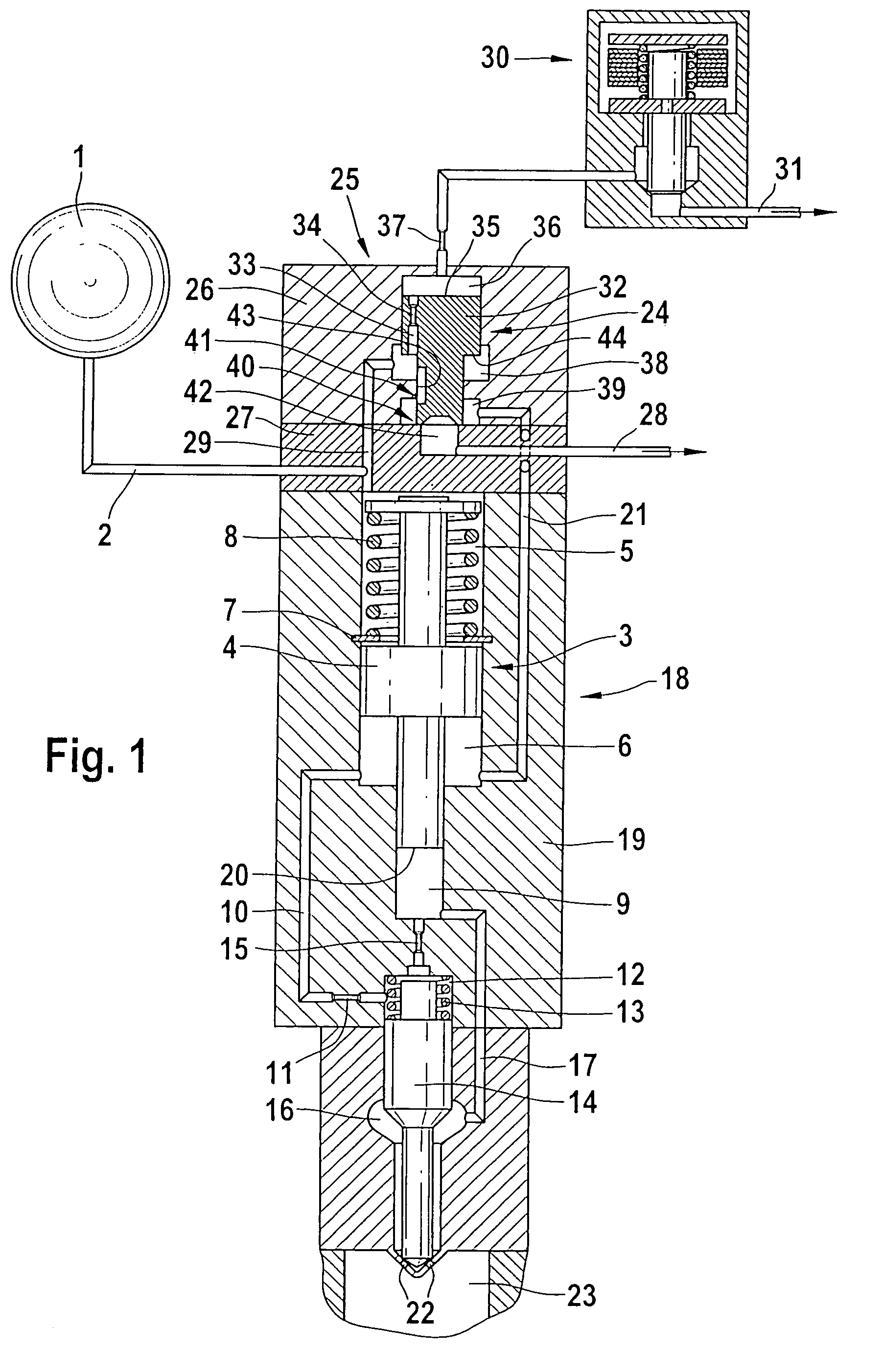
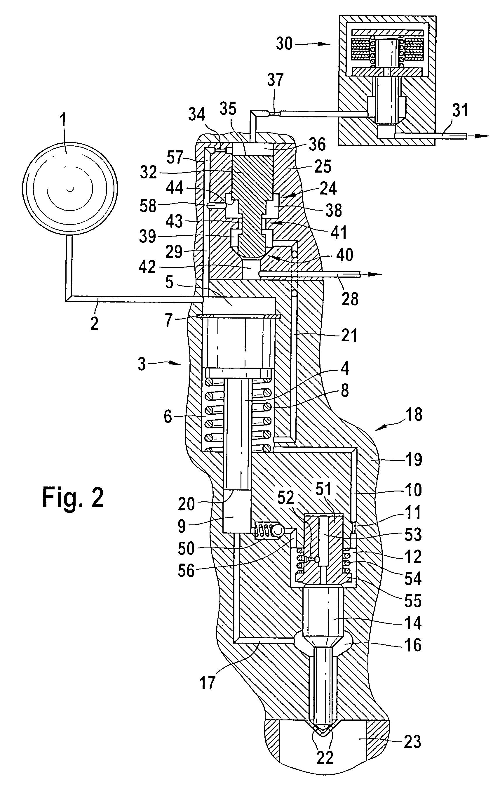
[0018]In FIG. 1, a first variant embodiment of a 3 / 2-way servo valve proposed according to the invention, for triggering a fuel injector that contains a pressure booster, can be seen. Via a pressure source 1 and a high-pressure supply line 2 connected to it, a work chamber 5 of a pressure booster 3 is subjected to fuel that is at high pressure. The work chamber 5 is subjected permanently to the fuel, at high pressure, of the pressure source 1. The pressure booster 3 includes a one-piece booster piston 4, which separates the work chamber 5 from a differential pressure chamber 6. The booster piston 4 is subjected to a restoring spring 8, which is braced on one end on a support disk 7 and on the other on a stop disk mounted on a protrusion of the booster piston 4. The differential pressure chamber 6 booster of pressure booster 3 communicates via an overflow line 10 with a control chamber 12 for an injection valve member 14. A first throttle restriction 11 is received in the overflow li...


PUM


Abstract

A fuel injector for injecting fuel into a combustion chamber of an internal combustion engine, including a pressure booster, whose booster piston separates a work chamber, subjected to fuel via a pressure reservoir, from a pressure-relievable differential pressure chamber. A pressure change in the differential pressure chamber is effected via an actuation of a servo valve, which opens or closes a hydraulic connection of the differential pressure chamber to a first low-pressure-side return. The servo valve has a piston guided between a control chamber and a first hydraulic chamber. On this servo valve piston, a hydraulic face that positions the servo valve piston constantly in the opening direction when system pressure is applied and a first sealing seat that closes or opens a low-pressure-side return are embodied.

Description

CROSS-REFERENCE TO RELATED APPLICATIONS[0001]This application is a 35 USC 371 application of PCT / DE 2004 / 000,413 filed on Mar. 4, 2004.BACKGROUND OF THE INVENTION[0002]1. Field of the Invention[0003]This invention relates to an improved fuel injection system for injecting fuel into internal combustion engines.[0004]2. Description of the Prior Art[0005]Stroke-controlled injection systems with a high-pressure reservoir (common rail) for introducing fuel into direct-injection internal combustion engines are known. The advantage of these injection systems is that the injection pressure can be adapted over wide ranges to the load and rpm. To reduce emissions and to attain high specific output, a high injection pressure is necessary. The attainable pressure level of high-pressure fuel pumps is limited for reasons of strength, so that to further increase the pressure in fuel injection systems, pressure boosters are used in the fuel injectors.[0006]For introducing fuel into direct-injection...

Claims


Application Information

Patent Timeline
Patent Type & Authority Patents(United States)
IPC IPC(8): F02M37/04F02M47/02F02M57/02F02M59/10F02M59/32F02M59/46F02M63/00F02M63/02
CPCF02M47/027F02M57/025F02M57/026F02M59/105F02M63/0015F02M63/0029F02M63/004F02M63/0043F02M63/0045F02M63/0225F02M2547/001
Inventor EISENMENGER, NADJAMAGEL, HANS-CHRISTOPH
Owner ROBERT BOSCH GMBH
Learn More