
Pressure sensing element and sensor incorporating the same

a technology of sensing element and sensor, applied in the field of pressure sensors, can solve the problems of thermal shock, which is generated, applied to the sensor chip, and strains the diaphragm of the sensor chip, and achieves the effect of preventing stress generation

Inactive Publication Date: 2008-01-22
DENSO CORP
View PDF8 Cites 12 Cited by
  • Summary
  • Abstract
  • Description
  • Claims
  • Application Information

AI Technical Summary

Benefits of technology

[0009]In view of the foregoing problem, it is an object of the present invention to provide a sensing element that can prevent stress generated at a joint portion from affecting a stress accepting portion if the sensing element is directly affixed to a case.
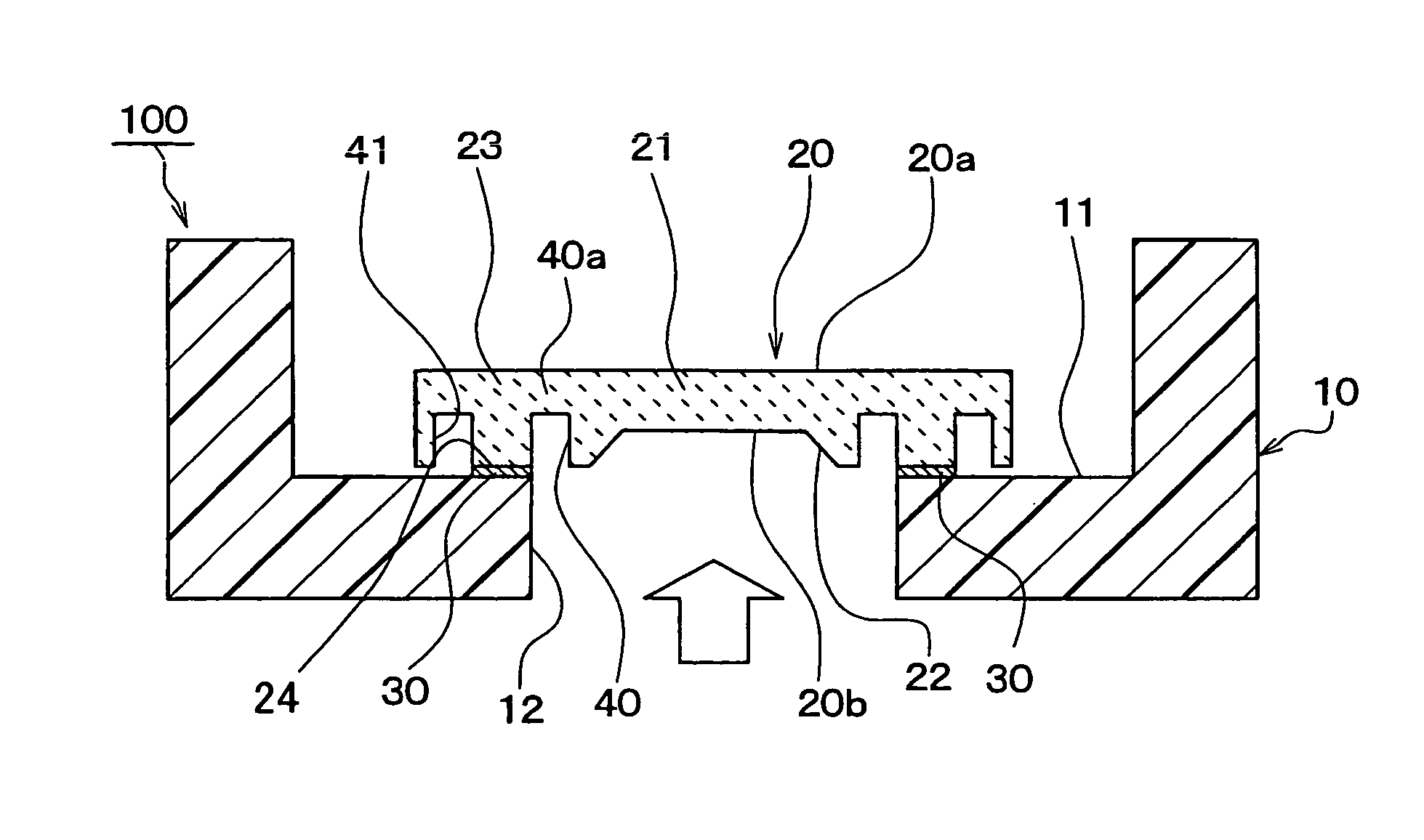
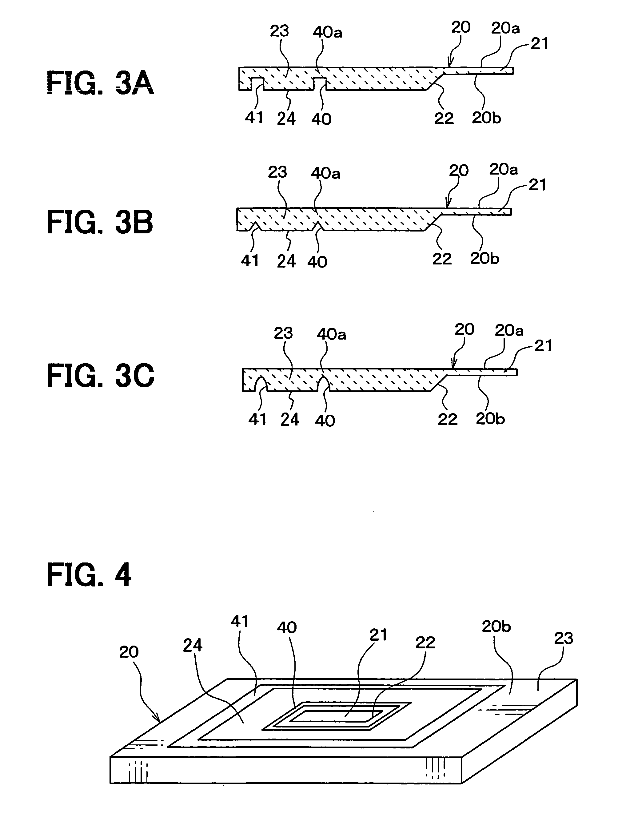
[0011]A sensing element according to a first aspect of the present invention includes a substrate having a stress-accepting portion and a joint portion, and a structure provided in the substrate and located between the stress-accepting portion and the joint portion for restraining stress in the substrate. The structure for restraining stress prevents stress that occurs at the joint portion from reaching the stress-accepting portion. Therefore, as the stress-accepting portion is isolated from the stress generated at the joint portion, the accuracy of the sensor output that is indicative of stress that is sensed at the stress-accepting portion is increased.
[0012]A sensing element according to a second aspect of the present invention includes a substrate having a stress-accepting portion and a joint portion, and a structure provided on a surface of the substrate at a side of the joint portion and located between the stress-accepting portion and the joint portion for pooling an adhesive. The structure for pooling an adhesive stores any excess adhesive that may be applied to adhere the sensing element to a sensor case and prevents the adhesive from flowing and adhering to the stress-accepting portion. Therefore, since the stress-accepting portion remains free of the adhesive, sensor accuracy is maintained while overall sensor cost is reduced, as a glass pedestal for separating the sensing element from the case is not required.

Problems solved by technology

Therefore, if the glass pedestal is omitted and the sensor chip is mounted directly on the case, thermal shock, which is generated during and after adhesion at the bonded part, is applied to the sensor chip.
This strains the diaphragm of the sensor chip and negatively affects the sensor characteristics.
This increases the possibility of that the sensor characteristics of the sensor chip are negatively affected.
This is because the surface tension of the adhesive used to bond this kind of sensor chip is generally small.

Method used


Image

  • Pressure sensing element and sensor incorporating the same
  • Pressure sensing element and sensor incorporating the same
  • Pressure sensing element and sensor incorporating the same

Examples


Embodiment Construction

[0019]Preferred embodiments according to the present invention will be described hereunder with reference to the accompanying drawings. In the drawings, the same reference numerals are given to the corresponding or similar parts, in order to simplify explanation.

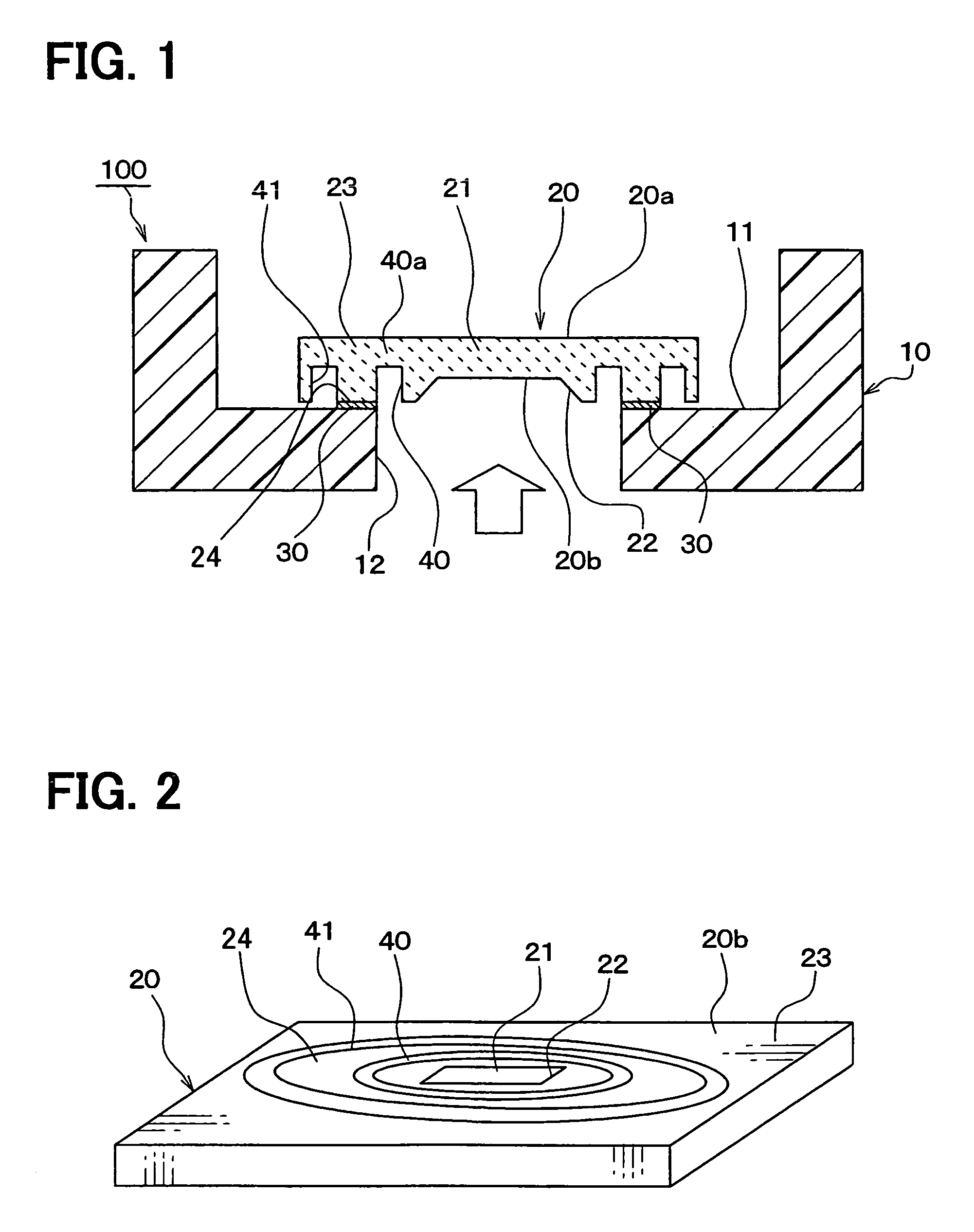
[0020]As shown in FIG. 1, a pressure sensor 100 of a first embodiment is equipped with a case 10 and a semiconductor sensor chip 20 for pressure sensing that is attached to the case 10. The sensor chip 20 has a diaphragm 21 as a pressure-sensitive portion, or more generally a stress-accepting portion that is distorted when pressure is applied thereto. The pressure sensor 100 is structured so that the sensor chip 20 is directly fixed by an adhesive 30 to the case 10.

[0021]The case 10 forms the outline of the pressure sensor 100, and is formed by molding a resin material, such as PBT (polybutylene terephthalate), PPS (polyphenylene sulfide) or the like. In addition, the case 10 may be fabricated from materials other than resin...


PUM

PropertyMeasurementUnit
stressaaaaaaaaaa
thickaaaaaaaaaa
pressureaaaaaaaaaa

Abstract

A pressure sensor includes a sensor chip in which a diaphragm is provided, and a case to which the sensor chip is directly mounted by an adhesive. A groove that surrounds the diaphragm is provided on the rear surface of the sensor chip between the bonded part and the diaphragm. The groove prevents thermal stress, which occurs at the bonded part, from reaching the diaphragm through the sensor chip, and thereby the accuracy of the sensor output is highly accurate. Further, the groove may store any excessive adhesive that may be applied when the sensor chip is bonded to the case to prevent the adhesive from flowing and adhering to the diaphragm.

Description

CROSS REFERENCE TO RELATED APPLICATION[0001]This application is based upon, claims the benefit of priority of, and incorporates by reference the contents of Japanese Patent Application No. 2005-038893 filed on Feb. 16, 2005.FIELD OF THE INVENTION[0002]The present invention relates generally to pressure sensors, and more specifically to a semiconductor pressure sensing element chip that has a diaphragm and that is joined directly to a case by an adhesive.BACKGROUND OF THE INVENTION[0003]Conventional semiconductor type pressure sensors include a sensor chip for sensing an applied pressure and a case for accommodating the sensor chip. The sensor chip includes a semiconductor substrate such as a silicon substrate and has a diaphragm that is deformable in accordance with an applied pressure.[0004]As disclosed in JP-A-H11-14480, a sensor chip of a conventional pressure sensor is fixed to the case via a glass pedestal. The glass pedestal has a through hole for introducing pressure to the d...

Claims


Application Information

Patent Timeline
Patent Type & Authority Patents(United States)
IPC IPC(8): G01L9/00
CPCG01L19/147
Inventor UENO, MASATO
Owner DENSO CORP
Learn More