
Method of mobile communication system with smart antenna

a mobile communication system and smart antenna technology, applied in the field of mobile communication, can solve the problems of no solution for the above problems, achieve the effects of improving system efficiency, improving quality of received packages, and improving system efficiency

Inactive Publication Date: 2008-01-15
DATANG MOBILE COMM EQUIP CO LTD
View PDF4 Cites 20 Cited by
  • Summary
  • Abstract
  • Description
  • Claims
  • Application Information

AI Technical Summary

Benefits of technology

The invention provides a method for transmitting high-speed downlink package data in a mobile communication system with a smart antenna. The method takes advantage of the smart antenna to make downlink beamforming and improve the transmission of the package data. The method includes steps of: 1. The radio base station with the smart antenna obtaining the initial direction of arrival (DOA) information of every subscriber terminal that is ready for receiving the package data. 2. The radio base station making downlink beamforming based on the initial DOA information. 3. The radio base station transmitting the downlink package data with the new beamforming until the current subscriber terminal has correctly received all downlink packages. 4. The current subscriber terminal detecting error codes of the downlink package data and acknowledging the data with a new downlink package. 5. The radio base station making a new downlink beamforming and transmitting the next downlink package to the next subscriber terminal if the current subscriber terminal has correctly received all downlink packages. 6. The method allows for the efficient transmission of high-speed downlink package data without occupying too much system resources.

Problems solved by technology

Up till now, there is no solution for the above problems.

Method used


Image

  • Method of mobile communication system with smart antenna
  • Method of mobile communication system with smart antenna
  • Method of mobile communication system with smart antenna

Examples


Embodiment Construction

[0039]The invention will be described in more detail with reference to drawings.

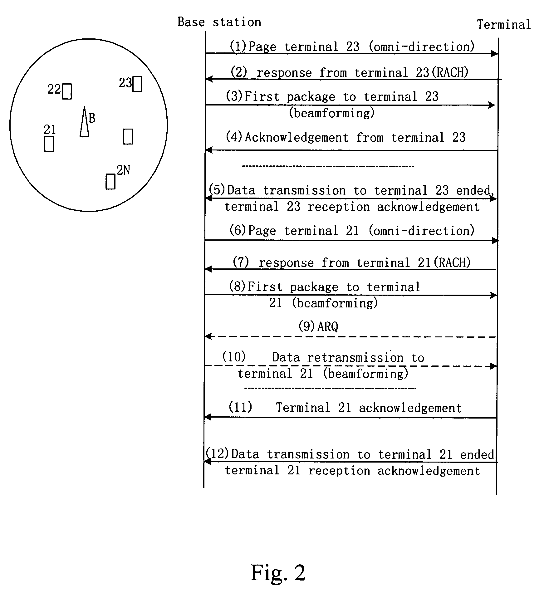
[0040]In FIG. 2, a mobile communication system with smart antenna knows that the subscriber terminals 21, 22, . . . 2N are all in the cell of base station B and at a ready state, but the system does not know the specific position (DOA) of these subscriber terminals.

[0041]When a radio base station with smart antenna transmits downlink package data to a subscriber terminal, the following steps are taken:

[0042]Step (1), based on system signaling, while the base station B makes transmission of downlink package data to subscriber terminal 23, 21, . . . 2N sequentially, first it calling first subscriber terminal 23 in a paging channel with omni-directional or sectored beam;

[0043]Step (2), having received the call, the called subscriber terminal 23 making an acknowledgement through a reverse access channel (RACH);

[0044]Step (3), after the call and response are successful, based on the received DOA of subscriber...


PUM


Abstract

The invention discloses a method for transmitting high-speed downlink package data in a mobile communication system with a smart antenna, which not only can take full advantage of radio beamforming of smart antenna but also can transmit downlink package data high efficiency. In this method, at the beginning of downlink package data transmission, no matter whether a subscriber terminal is at any state, a call for all ready subscriber terminal is made through a paging channel to obtain an initial DOA (direction of arrival) of every subscriber terminal, and then with this initial DOA the smart antenna transmits downlink package data to a subscriber terminal with an initial beamforming; having received one package, the subscriber terminal returns an acknowledgement message, if the downlink package is correctly received, or retransmission is required, if the received downlink package has error codes, so the system knows current position of the subscriber terminal and can use an updated beamforming to trace the subscriber terminal moving; based on received package quality, the system adaptively adjusts the length of a downlink package, and based on the moving speed of the subscriber terminal, the system adaptively adjusts the length of the downlink package too.

Description

FIELD OF THE TECHNOLOGY[0001]The invention relates generally to the mobile communication field, more specifically, to a method that not only can take full advantage of radio beamforming of smart antenna, but also can transmit downlink package data high efficiency in mobile communication system with smart antenna.BACKGROUND OF THE INVENTION[0002]In the future mobile communication system, transmission of high-speed downlink package data, i.e. data with Internet type, is an important service; the mobile communication system transmits this kind subscriber data based on the subscriber requirement.[0003]The present implementation method of this transmission may be described by taking a method in General Packet Radio Service (GPRS) of a Globe System for Mobile communication (GSM). The method works as follows: all accessed subscribers are in the ready state, i.e. connect to a network; the radio base station uses one carrier, and with one or multiple time slots of this carrier, the downlink ...

Claims


Application Information

Patent Timeline
Patent Type & Authority Patents(United States)
IPC IPC(8): H04M1/00H04L1/16H04B7/10H04B7/26H04J1/00H04W16/28
CPCH04W16/28H04W92/10
Inventor LI, SHIHEYANG, GUILIANG
Owner DATANG MOBILE COMM EQUIP CO LTD
Learn More