Optical information recording medium, optical information recording apparatus and method
a technology of optical information and recording medium, which is applied in the direction of recording strategies, instruments, optical beam sources, etc., can solve the problems of unclear recording of second information such as characters and figures, and achieve the effect of stably reproducing
- Summary
- Abstract
- Description
- Claims
- Application Information
AI Technical Summary
Benefits of technology
Problems solved by technology
Method used
Image

Examples
first embodiment
Description of First Embodiment
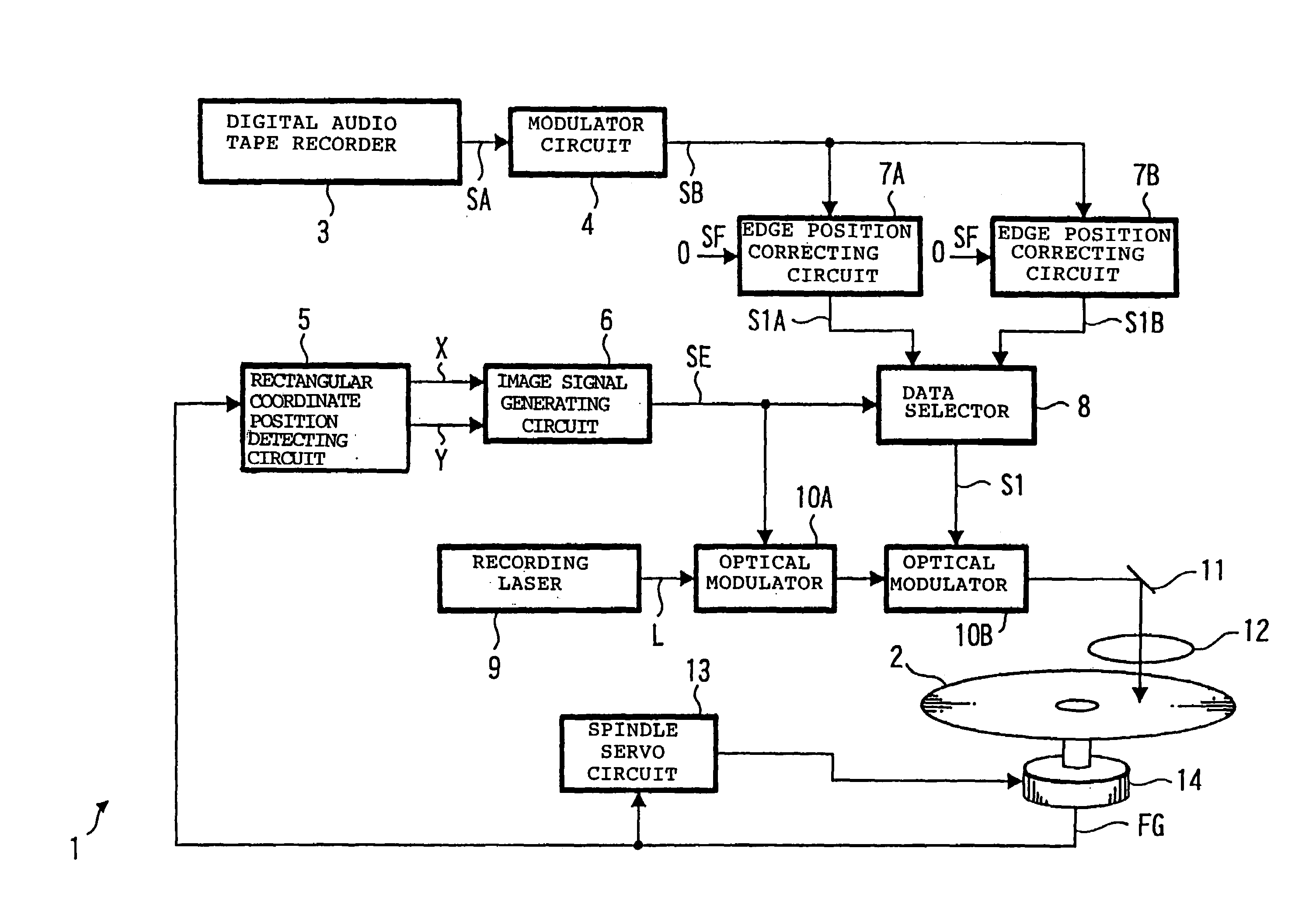
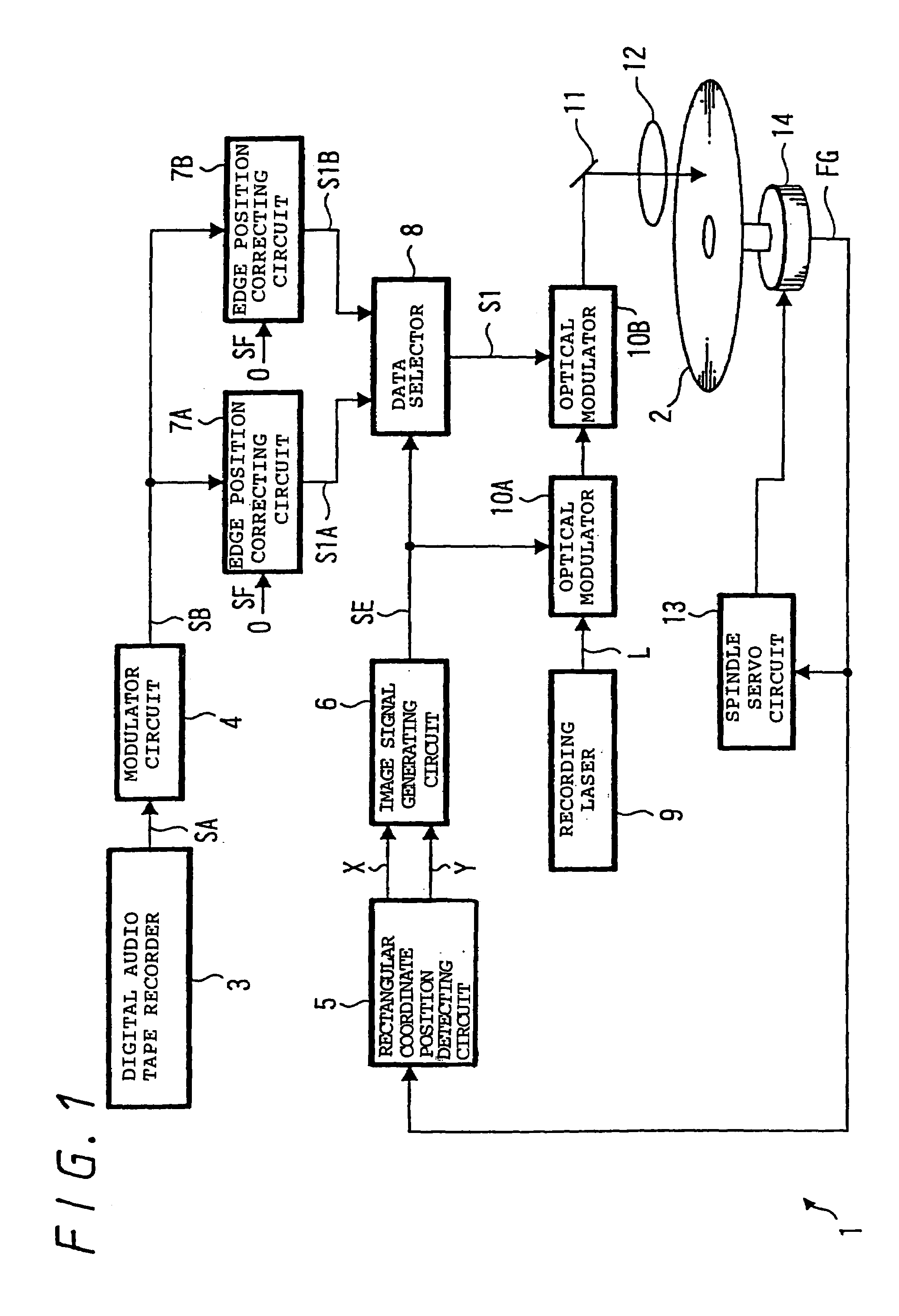
[0064]FIG. 1 is a block diagram showing an optical disk apparatus according to a first embodiment. The optical disk apparatus 1 exposes a disk master 2 so as to record an audio data SA outputted from a digital audio tape recorder 3 therein. At this time, a power of laser beam L used for exposure is varied according to a predetermined image data, and thus, a predetermined image and character are visibly recorded on an information recording surface of a compact disk. In a manufacturing process of an optical disk, the disk master 2 is developed, and thereafter, is subjected to electro-forming, and thereby, a master disk is prepared, and then, a stamper is manufactured with the use of a mother disk. Further, in the manufacturing process of an optical disk, a disk substrate is prepared by the stamper thus prepared, and then, a reflection film and a protection film are formed on the disk substrate, and thus, a compact disk is manufactured.
[0065]More specific...
second embodiment
Description of Second Embodiment
[0104]A second embodiment of the present invention will be detailedly described below with reference to the accompanying drawings.
[0105]FIG. 13 is a block diagram showing a construction of an optical disk apparatus according to a second embodiment of the present invention. In FIG. 13, like reference numerals are used to designate the parts corresponding to those shown in FIG. 1, and the details are omitted.
[0106]The second information outputted from the character signal generating circuit 6, obtained in the manner as described in FIG. 1, is inputted to a staircase waveform generating circuit 130. The staircase waveform generating circuit 130 detects a change of the second information, and then, generates 3-bit staircase signal SF such that an output value stepwise varies together with time. The staircase signal SF is converted into a signal SX having a stepwise voltage by means of a voltage converter circuit 132, and then, is inputted to an optical mo...
third embodiment
Description of Third Embodiment
[0138]A third embodiment of the present invention will be described below with reference to the accompanying drawings.
[0139]FIG. 18 is a block diagram showing a construction of an optical disk apparatus according to the third embodiment. In FIG. 18, like reference numerals are used to designate the parts corresponding to those shown in FIG. 1, and the details are omitted.
[0140]A second modulation circuit 180 inputs the EFM modulation signal SB and the second information SE, and overlaps the second information SE with the EFM modulation signal SB so as to hinder a recording information to be recorded as an EFM signal, and thus, outputs an signal SD.
[0141]The second modulation circuit 180 has a construction as shown in FIG. 19. In this case, a PLL circuit 190 generates a channel clock CK which varies every the minimum change unit of the EFM signal SB, and then, supplies the channel clock CK to a signal overlapping circuit 191 and a timing correcting circ...
PUM
| Property | Measurement | Unit |
|---|---|---|
| radius | aaaaa | aaaaa |
| radius | aaaaa | aaaaa |
| radius | aaaaa | aaaaa |
Abstract
Description
Claims
Application Information
 - R&D
- Intellectual Property
- Life Sciences
- Materials
- Tech Scout
- Unparalleled Data Quality
- Higher Quality Content
- 60% Fewer Hallucinations
Browse by: Latest US Patents, China's latest patents, Technical Efficacy Thesaurus, Application Domain, Technology Topic, Popular Technical Reports.
© 2025 PatSnap. All rights reserved.Legal|Privacy policy|Modern Slavery Act Transparency Statement|Sitemap|About US| Contact US: help@patsnap.com