Eureka AIR delivers breakthrough ideas for toughest innovation challenges, trusted by R&D personnel around the world.

Rotation angle detecting device

a detection device and rotation angle technology, applied in the direction of measurement devices, magnetic field-controlled resistors, instruments, etc., can solve problems such as detection error of rotation angle, and achieve the effect of improving rotation angle detection

Inactive Publication Date: 2008-01-15
DENSO CORP +1
View PDF10 Cites 47 Cited by
  • Summary
  • Abstract
  • Description
  • Claims
  • Application Information

AI Technical Summary

Benefits of technology

[0006]Therefore, it is an object of the invention to provide an improved rotation angle detecting device that is free from the above described inconvenience.
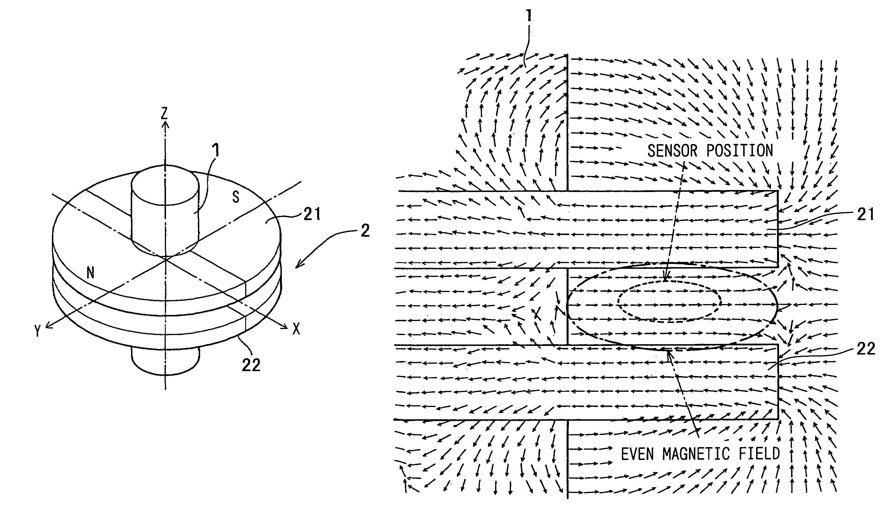
[0007]According to a feature of the invention, a rotation angle detecting device for detecting a relative rotation of two members includes a magnet unit fixed to the first member and a pair of magnetic sensors fixed to the second member to provide output signals whose phase is different from each other at 90 degrees in angle. In the above device, the magnet unit includes a pair of disk plates that has the same magnetic poles at the same circumferential positions and is disposed at a prescribed axial distance and a shaft that is made of magnetic material to support the disk plates at the center thereof. Therefore, the magnetic unit provides a uniform magnetic field in a space around the shaft between the pair of disk plates, in which the pair of magnetic sensors is disposed. Accordingly, errors in the detected rotation angle can be substantially eliminated even if there is variations in position of the magnetic sensors so that output variations of the magnetic sensor to the detected rotation angle can be substantially eliminated

Problems solved by technology

Accordingly, the output signal of the magnetic sensor may vary if the position of the magnetic sensor is shifted, resulting in a detection error of the rotation angle.

Method used


Image

  • Rotation angle detecting device
  • Rotation angle detecting device
  • Rotation angle detecting device

Examples


Embodiment Construction

[0017]A rotation angle detecting device according to the first embodiment of the invention will be described with reference to FIGS. 1-5 of the appended drawings.

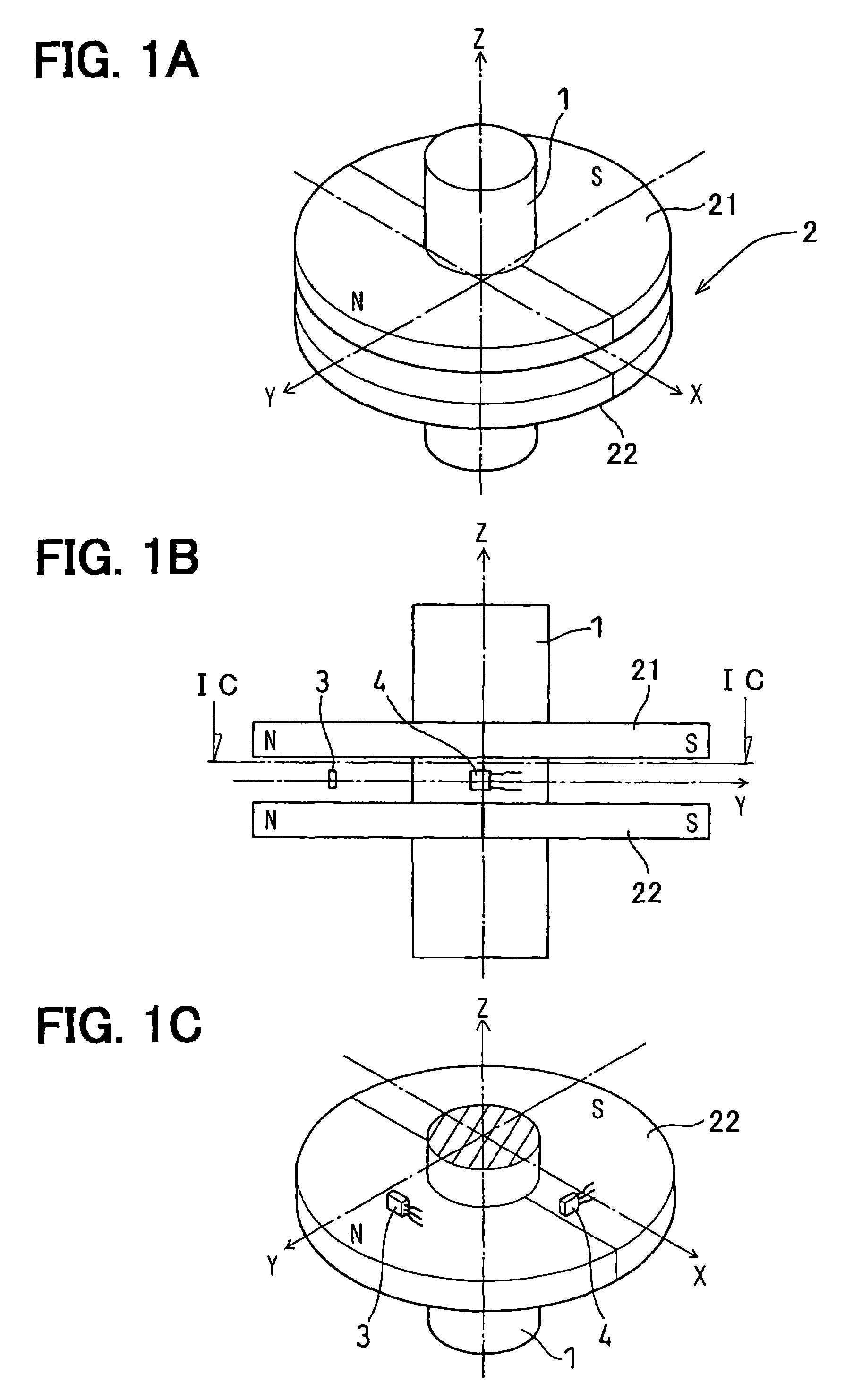
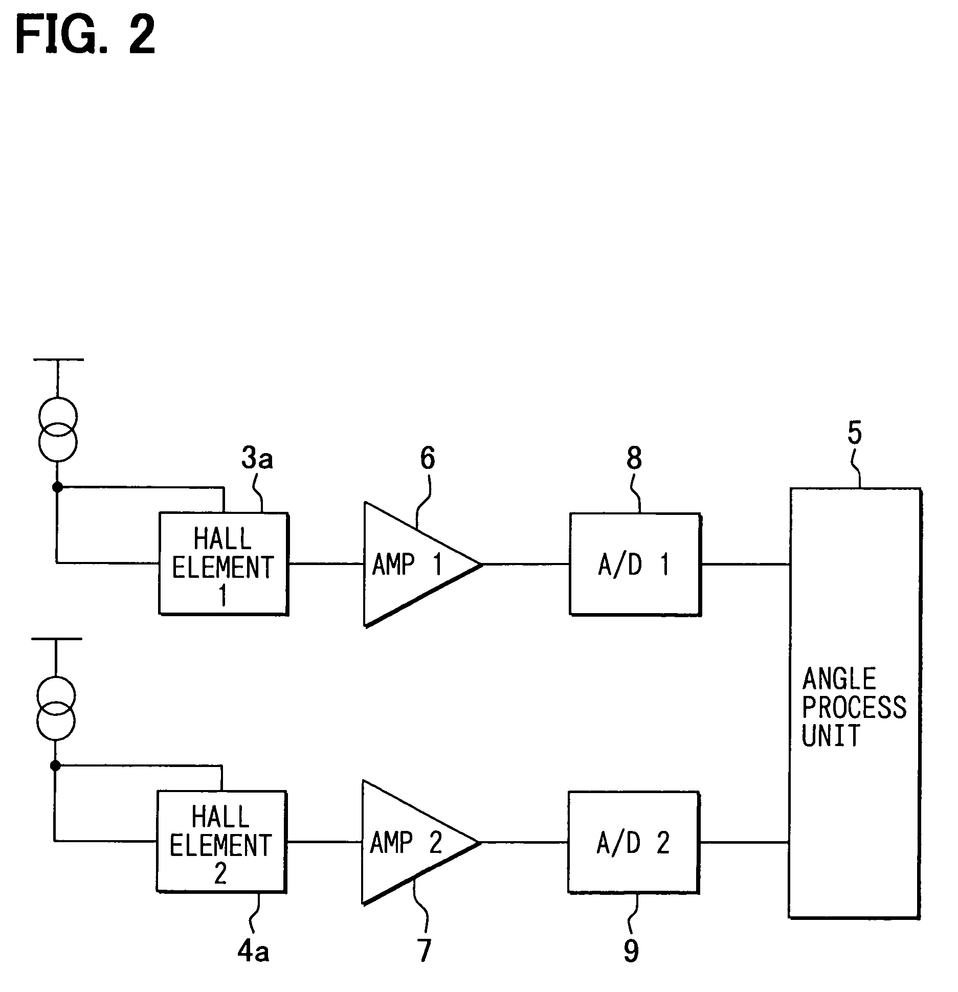
[0018]The rotation angle detecting device includes a shaft 1, a permanent magnet unit 2, a pair of magnetic sensors 3, 4 and an angle processing unit 5. The shaft 1 is a pole member made of a magnetic material such as iron and is connected to an outside member such as a rotating shaft of a throttle valve. The permanent magnet unit 2 is constituted of a pair of magnet disks 21, 22, which are supported by the shaft 1 at a certain distance in the axial direction to rotate together therewith. The magnet disks 21, 22 have an axis Z and a pair of radially magnetized magnetic poles N, S at opposite positions (at an interval of 180 degrees) on its periphery. The magnet disks 21, 22 are the same both in size and magnetic characteristics. Accordingly, a closed magnetic field is formed in the space around the shaft 1 between the magne...


PUM


Abstract

An improved rotation angle detecting device that detects a rotation angle of a first member relative to a second member is proposed. The rotation angle detecting device includes a magnet unit fixed to the first member and a pair of magnetic sensors fixed to the second member to provide output signals whose phase is different from each other at 90 degrees in angle. The magnet unit includes a pair of disk plates that has the same magnetic poles at the same circumferential positions and is disposed at a prescribed axial distance and a shaft that is made of magnetic material to support the disk plates at the center thereof. The magnetic unit provides a uniform magnetic field in a space around the shaft between the pair of disk plates, and a pair of magnetic sensors is disposed in the space.

Description

CROSS REFERENCE TO RELATED APPLICATION[0001]The present application is based on and claims priority from Japanese Patent Application 2004-231636, filed Aug. 6, 2004, the contents of which are incorporated herein by reference.BACKGROUND OF THE INVENTION[0002]1. Field of the Invention[0003]The present invention relates to a rotation angle detecting device for detecting a relative rotation angle between two members without contacting the members.[0004]2. Description of the Related Art[0005]JP-A-2003-75108 discloses a rotation angle detecting device that detects a relative rotation angle of one member to another member by means of a permanent magnet and a pair of magnetic sensors. The pair of magnetic sensors is fixed to the one member to be spaced apart from the other at 90 degrees in angle and disposed to confront the permanent magnet that is fixed to the other. Therefore, magnetic sensors are disposed near the permanent magnet, which forms an open magnetic field. That is, the lines o...

Claims


Application Information

Patent Timeline
Patent Type & Authority Patents(United States)
IPC IPC(8): G01B7/14G01R33/06H01L43/06H01L43/08
CPCG01D5/145
Inventor KAWASHIMA, TAKASHIMATSUMOTO, KOICHIROKITANAKA, TATSUYABAN, TAKAOTAKEDA, KENJINAKAMURA, TSUTOMUSHIMOMURA, OSAMU
Owner DENSO CORP
Why Eureka
Eureka Blog
Learn More