Humidity control apparatus

a technology of humidity control and humidification apparatus, which is applied in the direction of lighting and heating apparatus, domestic cooling apparatus, heating types, etc., can solve the problems of reducing the moisture content of the supply air, failing to provide a sufficient humidification capacity, and insufficient capacity, so as to improve the humidification capacity and efficiency of use. , the effect of efficient us

Inactive Publication Date: 2008-01-15
DAIKEN CORP
View PDF14 Cites 3 Cited by
  • Summary
  • Abstract
  • Description
  • Claims
  • Application Information

AI Technical Summary

Benefits of technology

[0071]Therefore, according to the first and eighth solutions, it is possible to reduce the limitations on the layout of the components of the humidity control apparatus, particularly, the first heat exchanger (103) and the second heat exchanger (104), which may each serve as an evaporator. Thus, it is possible to reliably avoid problems that may occur due to the limitations on the layout of the components, i.e., a decrease in the design freedom of the humidity control apparatus, or the air passageways becoming complicated to increase the size of the humidity control apparatus.
[0072]In the second to fifth and ninth to twelfth solutions, the refrigerant circuit (100) is configured to perform various operations. Therefore, these solutions make possible various operations of the refrigerant circuit (100), thereby increasing the functionality of the humidity control apparatus.
[0044]According to the sixth solution, the humidity control apparatus can perform an operation in which the first heat exchanger (103) of the refrigerant circuit (100) serves as an evaporator when the first air dehumidified in the adsorption operation is supplied into the room while the second air humidified by the regeneration operation is discharged to the outside. In this operating mode, the first air to be supplied into the room is cooled through the first heat exchanger (103). Thus, the first air is dehumidified through the adsorbing element (81, 82) and then cooled through the first heat exchanger (103) before it is supplied into the room.
[0074]According to the thirteenth and fourteenth solutions, it is possible to perform an operation in which the first air is dehumidified and then further cooled before it is supplied into the room, while heat collected from the second air to be discharged is reused for heating the second air in the regenerative heat exchanger (102). Therefore, with this operation, it is possible not only to control the humidity of, but also to cool, the air in the room, while the internal energy of the second air to be discharged can be efficiently used for the operation of the humidity control apparatus.
[0074]According to the thirteenth and fourteenth solutions, it is possible to perform an operation in which the first air is dehumidified and then further cooled before it is supplied into the room, while heat collected from the second air to be discharged is reused for heating the second air in the regenerative heat exchanger (102). Therefore, with this operation, it is possible not only to control the humidity of, but also to cool, the air in the room, while the internal energy of the second air to be discharged can be efficiently used for the operation of the humidity control apparatus.
[0076]According to the seventeenth and eighteenth solutions, it is possible to perform an operation in which the first air is dehumidified and then further cooled before it is supplied into the room, while the refrigerant radiates heat into the second air both in the regenerative heat exchanger (102) and in the second heat exchanger (104). Therefore, with this operation, it is possible not only to control the humidity of, but also to cool, the air in the room. Moreover, the enthalpy of the refrigerant passed to the first heat exchanger (103) serving as an evaporator can be reduced, whereby the amount of heat absorbed by the refrigerant through the first heat exchanger (103) can be increased, thus improving the cooling capacity.
[0077]According to the nineteenth and twentieth solutions, it is possible to perform an operation in which the second air is humidified and then further heated before it is supplied into the room, while heat collected from the first air to be discharged is used for heating the second air in the regenerative heat exchanger (102) or the first heat exchanger (103). Therefore, with this operation, it is possible not only to control the humidity of, but also to heat, the air in the room, while the internal energy of the first air to be discharged can be efficiently used for the operation of the humidity control apparatus.
[0078]According to the twenty-first to twenty-fourth solutions, in an operation where the first heat exchanger (103) and the second heat exchanger (104), which are arranged in series with each other, both serve as an evaporator, it is possible to reduce the amount of heat absorbed by the refrigerant through one of the heat exchangers (103, 104) that is located downstream of the other. Thus, the amount of heat absorbed by the refrigerant through the first and second heat exchangers (103, 104) both serving as an evaporator can be kept in balance with the amount of heat radiated from the refrigerant through the regenerative heat exchanger (102) serving as a condenser, whereby it is possible to perform a stable refrigerating cycle in the refrigerant circuit (100).
[0074]According to the thirteenth and fourteenth solutions, it is possible to perform an operation in which the first air is dehumidified and then further cooled before it is supplied into the room, while heat collected from the second air to be discharged is reused for heating the second air in the regenerative heat exchanger (102). Therefore, with this operation, it is possible not only to control the humidity of, but also to cool, the air in the room, while the internal energy of the second air to be discharged can be efficiently used for the operation of the humidity control apparatus.

Problems solved by technology

However, the conventional humidity control apparatus described above has a configuration that is made only in view of the dehumidification mode for dehumidifying the air to be supplied into the room, and cannot provide a sufficient capacity when it is used in the humidification mode for humidifying the air to be supplied into the room.
Thus, with the humidity control apparatus, the moisture contained in the supply air is reduced as the supply air passes through the evaporator, failing to provide a sufficient humidification capacity.

Method used


Image

  • Humidity control apparatus
  • Humidity control apparatus
  • Humidity control apparatus

Examples


embodiment 1

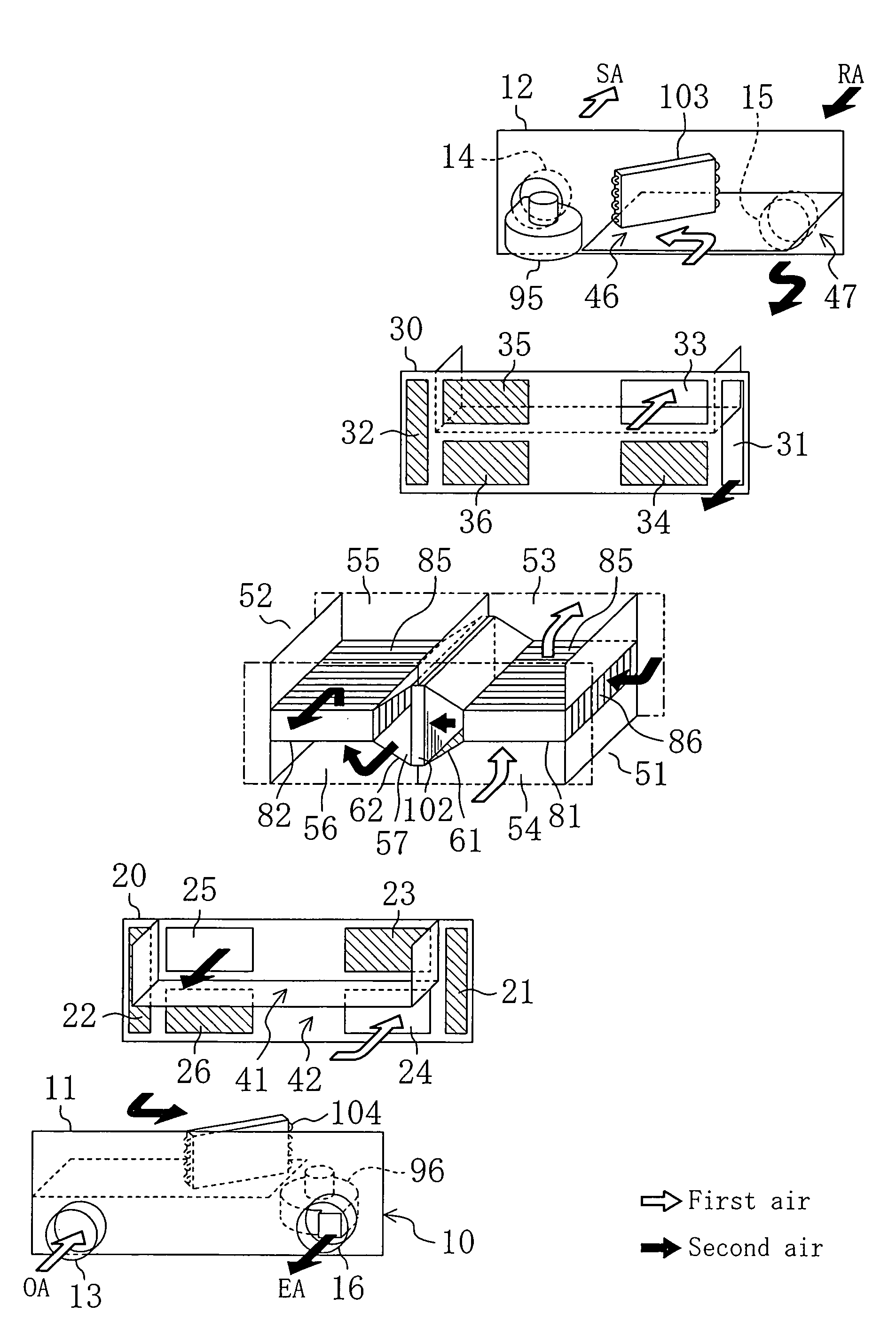
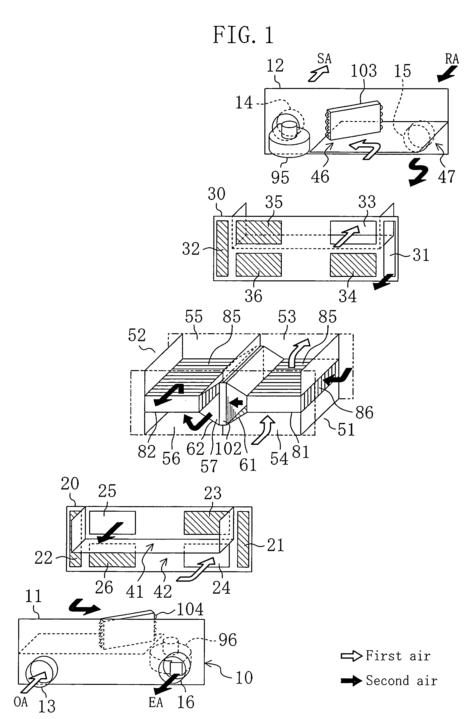
[0110]A humidity control apparatus according to the present embodiment is switched between the dehumidification mode in which a dehumidified air is supplied into the room and the humidification mode in which a humidified air is supplied into the room. Moreover, the humidity control apparatus includes a refrigerant circuit (100) and two adsorbing elements (81, 82), and performs a so-called “batch” operation. The configuration of the humidity control apparatus according to the present embodiment will now be described with reference to FIG. 1, FIG. 5, FIG. 6 and FIG. 7.

[0111]General Configuration of Humidity Control Apparatus

[0112]As illustrated in FIG. 1 and FIG. 5, the humidity control apparatus includes a casing (10) having a somewhat flattened, rectangular parallelepiped shape. The casing (10) accommodates the two adsorbing elements (81, 82) and the refrigerant circuit (100). The refrigerant circuit (100) includes a regenerative heat exchanger (102), a first heat exchanger (103) an...

embodiment 2

Effects of Embodiment 2

[0238]According to the present embodiment, the following effects are realized in addition to those obtained in Embodiment 1.

[0239]Specifically, with the humidity control apparatus of the present embodiment, in the dehumidification mode, heat collected from the second air to be discharged can be reused for heating the second air in the regenerative heat exchanger (102). Therefore, with the humidity control apparatus, the internal energy of the second air to be discharged can be efficiently used for the operation of the humidity control apparatus.

[0240]Moreover, with the humidity control apparatus of the present embodiment, in the humidification mode, heat collected from the first air to be discharged can be used for heating the first air in the regenerative heat exchanger (102). Therefore, with the humidity control apparatus, the internal energy of the first air to be discharged can be efficiently used for the operation of the humidity control apparatus.

[0241]M...

embodiment 3

Effects of Embodiment 3

[0282]According to the present embodiment, the following effects are realized in addition to those obtained in Embodiments 1 and 2.

[0283]Specifically, with the humidity control apparatus of the present embodiment, in the third operating mode of the humidification mode, the second air can be humidified and then further heated before it is supplied into the room. Therefore, the humidity control apparatus can not only control the humidity of, but also heat, the air in the room. Moreover, in the refrigerant circuit (100) in this mode, the regenerative heat exchanger (102) and the first heat exchanger (103), which both serve as a condenser, are parallel to each other. Therefore, as compared with a case where the regenerative heat exchanger (102) and the first heat exchanger (103) both serving as a condenser are in series with each other, the amount of heat to be given from the refrigerant to the second air through the first heat exchanger (103) can be increased, th...


PUM


Abstract

A humidity control apparatus includes two adsorbing elements (81, 82), and performs a batch-type operation. The humidity control apparatus includes a refrigerant circuit (100). A second air for regenerating the adsorbing element (81, 82) is heated through a regenerative heat exchanger (102) of the refrigerant circuit (100). The refrigerant circuit (100) includes a first heat exchanger (103) and a second heat exchanger (104). In a dehumidification mode, the first heat exchanger (103) serves as an evaporator, and the first air to be supplied exchanges heat with the refrigerant. At this point, the second heat exchanger (104) is inactive. In a dehumidification mode, the second heat exchanger (104) serves as an evaporator, and the first air to be discharged exchanges heat with the refrigerant. At this point, the first heat exchanger (103) is inactive.

Description

TECHNICAL FIELD[0001]The present invention relates to a humidity control apparatus for controlling the humidity of the air.BACKGROUND ART[0002]A humidity control apparatus using a so-called “desiccant rotor” and a heat pump in combination with each other has been known in the art, as disclosed in Japanese Laid-Open Patent Publication No. 9-329371. In such a humidity control apparatus, the condenser of the heat pump is provided along the air passageway for regeneration, and the evaporator of the heat pump is provided along the supply air passageway for supplying the air into the room. The humidity control apparatus performs an operation of dehumidifying the supply air for ventilation through the desiccant rotor and supplying the air into the room while regenerating the desiccant rotor with the discharge air for ventilation.[0003]Specifically, the outside air is taken into the humidity control apparatus as the supply air for ventilation. The outside air is dehumidified through the des...

Claims


Application Information

Patent Timeline
Patent Type & Authority Patents(United States)
IPC IPC(8): F25D17/06F24F3/14F24F3/147F24F3/153F25B5/00F25B5/04F25B6/04F25B13/00F25B29/00
CPCF24F3/1411F24F3/153F25B5/00F25B13/00F24F3/1429F25B5/04F25B6/04F25B2313/023F25B2313/0272
Inventor YABU, TOMOHIROXI, GUANNAN
Owner DAIKEN CORP
Why Eureka
Try Eureka