Quantitative dosing of small amounts of liquids

a technology of liquid dosing device and small amount, which is applied in the direction of liquid/fluent solid measurement, container, measuring chamber, etc., can solve the problems of inability to ensure the reproducibility required in precise dosing of small liquid dose, the need for long piezo rod and high voltage source dangerous to the user, and the inability to accelerate the movement of servo motors. achieve the effect of speeding up the separation of droplets

Inactive Publication Date: 2008-01-08
FLUILOGIC OYU
View PDF10 Cites 4 Cited by
  • Summary
  • Abstract
  • Description
  • Claims
  • Application Information

AI Technical Summary

Benefits of technology

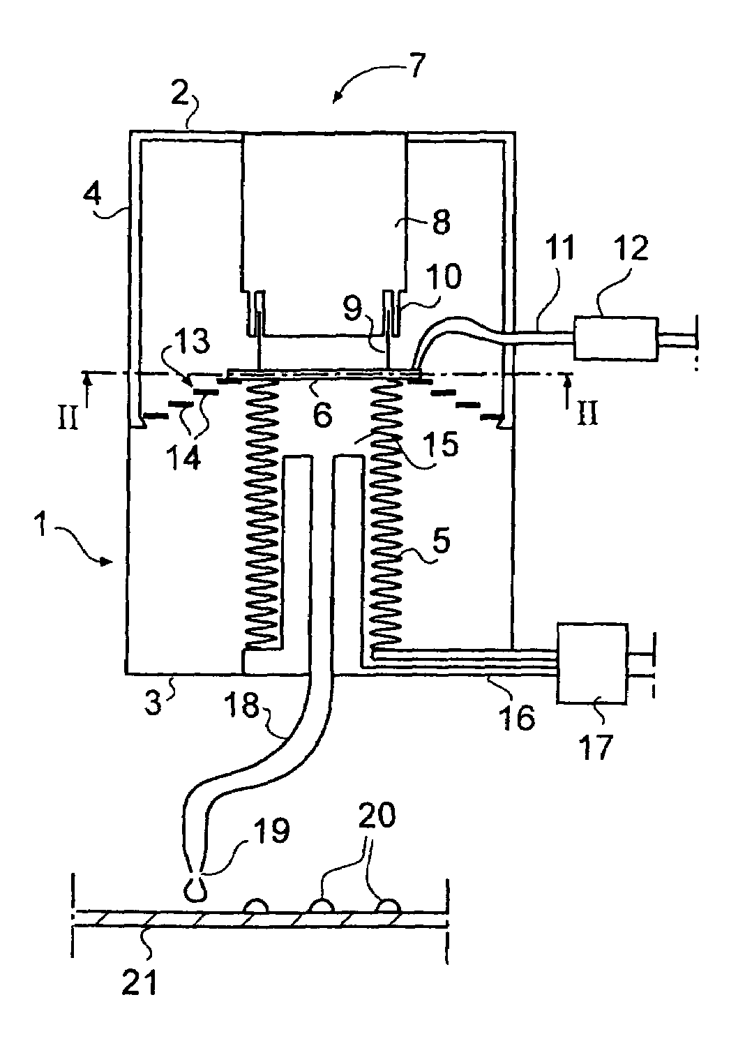
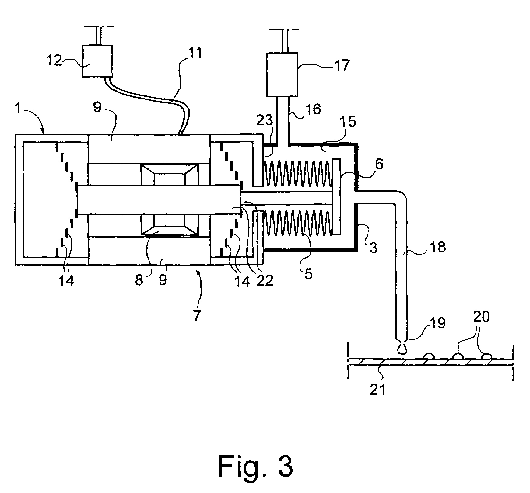
[0013]A characteristic feature of said actuator of the bellows formed of magnetic parts is the fact that electric current passing through the coil may be continuously controlled. This fact enables the precise adjustment of the selected length of the paths of the actuator and the bellows connected directly thereto without any transmitting means and consequently, the precise adjustment of the selected volume of the dosed liquid dose without the limitations due to the length of the step of the stepping motor used in prior art dosing means with bellows. Coils suitable for this purpose converting the magnetic field, altering by a changing electric current, into an attracting or repelling force acting on the bellows are known as such and commercially available for instance as sound coils for acoustic loudspeakers. Typically, the weight of the coil being some grams and the maximum repelling force being several kiloponds, the coil is able to produce small movements setting precisely with a very high acceleration for these parameters. The high-speed operation as such is an advantage when using the device for long serial dosing of hundreds of successive liquid doses, and it particularly enables the dosing of liquid from the dosing tip as small droplets into the air as described in more detail below in connection with the description of the dosing methods of the invention.
[0016]In case the spring forces of the bellows and the centralizer mutually act in opposite directions, a balance point where the spring forces cancel each other may be found for the end of the bellows and where the end of the bellows rests if the current coil of the actuator has no electric current. This zero position of the end of the bellows lies in the path thereof, preferably near the middle or even precisely in the middle of said path, thus enabling the end of the bellows to move on both sides of this zero position depending on the direction of the electric current passing through the current coil. This arrangement is advantageous for instance in long serial dosing of a high number of successive liquid doses wherein the liquid space is filled with the liquid to be dosed and dosing is started from the extreme position of the end of the bellows to dose step by step successive liquid doses first by gradually decreasing the electric current passing through the current coil to reduce the magnetic attracting force of the actuator, and following the passing-by of the zero position, dosing is continued by reversing the direction of the electric current passing through the current coil and thus gradually increasing the magnetic repelling force of the actuator, until the serial dosing is completed as the end of the bellows reaches the opposite end of its movement path. Said zero position and the change of the direction of the electric current at that position enable the spring force acting against the actuator to remain as small as possible during the serial dosing. The lower the proportion of the attracting and repelling forces of the coil needed to surmount the action of the spring, the higher the force that may be used for the accelerations required in precise dosing of small amounts of liquids.
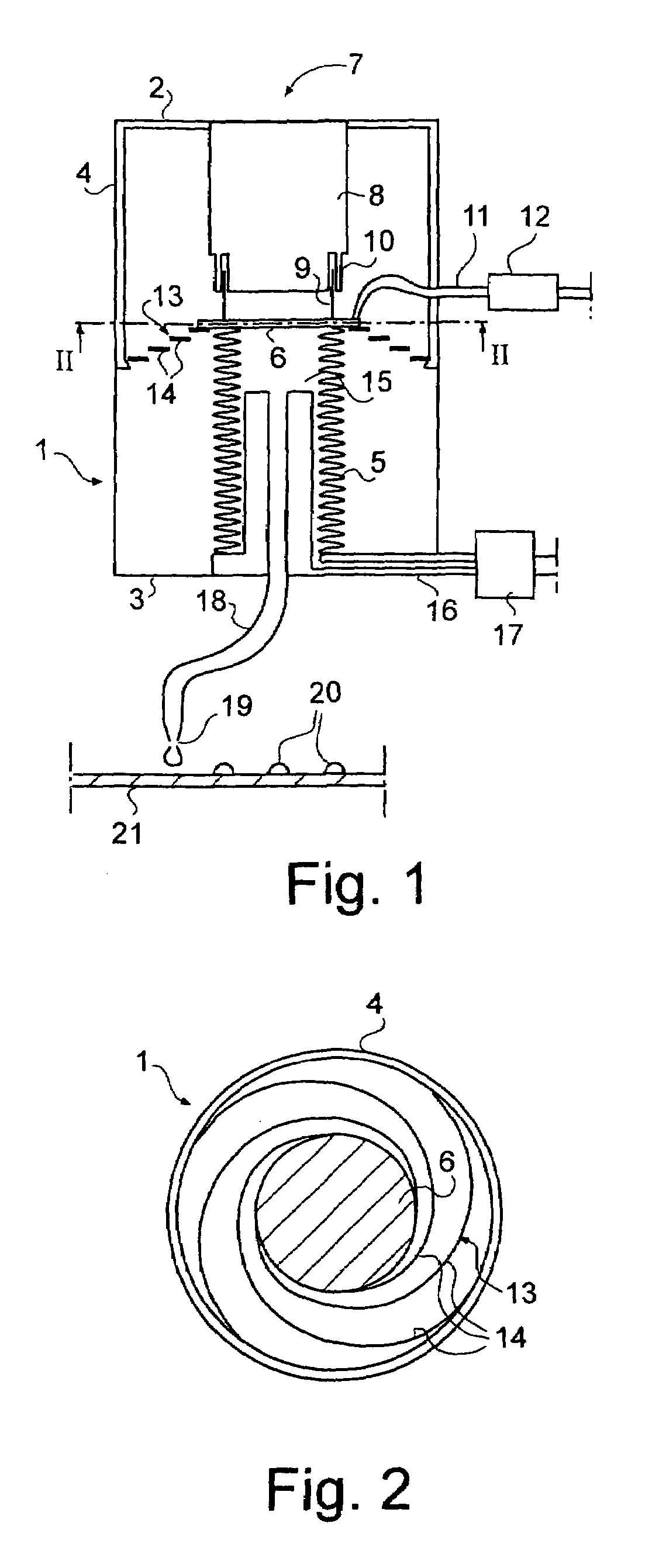
[0017]In a simple configuration of the device of the invention, the body of the device comprises a cylindrical jacket. The bellows and the moving part of the actuator connected thereto are sequentially arranged into the space defined by the jacket on the middle axis thereof. This arrangement enables the formation of the centralizer from springs, one end thereof being connected to the inner surface of the jacket and the other end being connected to the moving parts of the device.
[0018]In the device, the liquid space defined by the bellows may lie either within or without the bellows. The liquid space may be provided with a separate filling channel for the liquid to be dosed, the only task of the dosing tip thus being the discharging of the liquid doses. This helps to reduce the transfer movements required in dosing and promote the effective use of the dosing tip.
[0023]In applying the described droplet dosing to a serial dosing, the numerical value of the change of the electric current in the second step slowing down the bellows must be smaller than that of the change in the first step. It is further possible to draw some air into the dosing tip with the bellows before dosing of each individual liquid droplet to speed up the separation of the droplet.

Problems solved by technology

Main drawbacks of such dosing devices are the sliding friction between the cylinder and the piston and unpreciseness of the setting in motion and stopping of the piston, and as a consequence, reproducibility required in precise dosing of small liquid doses is not assured.
However, the same limitations with respect to the acceleration of the movement apply both to the servo motor and to the stepping motor.
Particularly, a drawback of the piezo rod is in turn the fact that a long piezo rod and high voltage source dangerous to the user are needed for the path of the bellows required in dosing a high number of liquid doses successively.
In this case, the masses of the rod and moving auxiliary devices as well as the operation time thereof also become an obstruction to the sufficient acceleration of the movement.
Thus, said publication teaches no solution enabling the precision dosing of liquid amounts of nanoliter order.
The technique is however based on the fact that several successive droplets are focused on the same point, the size of individual droplets being not precisely controlled.
The technique applied in printers is not a suitable solution to quantitative dosing of liquids.
The disadvantage of the prior art is thus the lack of a technique enabling the quantitative dosing of liquid amounts measuring only nanoliters.

Method used


Image

  • Quantitative dosing of small amounts of liquids
  • Quantitative dosing of small amounts of liquids
  • Quantitative dosing of small amounts of liquids

Examples


example 1

[0035]The invention was tested with nickel / cobalt-bellows defining an inner liquid space with a cross section of 50 mm2, the length of the path of the end of the bellows being 1.5 mm. The end of the bellows was moved with an acoustic coil LA08-10 producing an instantaneous compressing force of 0.9 kg, the coil being controlled by a 16 bit DA-converter using an Omega Engineering CIO-DAC02-16-controller card and the control program thereof. Effective dosing volume of the bellows is about 60 μl, and for said coil and DA converter, the smallest liquid volume that may be dosed is calculated to be about 1 nl. In the test, 20 doses of water having respectively a volume of 250 nl (250 μg), and 20 doses of water having respectively a volume of 15 nl (15 μg) were serially dosed directly into the receiving liquid having a volume of 2 ml, using liquid contact. Doses were determined by weighing the receiving liquid with a Mettler MT 5 balance before and after each dosing and by calculating the w...

example 2

[0036]In the test, nickel / cobalt bellows having a diameter of 12.5 mm were used, the highest dosing volume corresponding to the length of the path of the end of the bellows being about 100 μl. The bellows were moved by an acoustic coil LA13-12 controlled by a DA converter of Example 1. The orifice of the dosing tip was 0.35 mm.

[0037]The liquid to be dosed was a thick, heterogenous liquid reagent containing solid particles having a 7-fold viscosity compared to water.

[0038]Dosing was carried out as droplet dosing using the technique described above, first accelerating and then slowing down the movement of the liquid for sharp release of the droplet from the dosing tip. 20 liquid doses having respectively a volume of 1.5 μl were serially dosed, each time starting dosing by changing the magnitude of the electric current passed through he coil by a value corresponding to a volume change of the dosing space of 6 μl. The repelling force of the coil was thus 4-fold compared to the force alr...

example 3

[0039]Dilute dimethyl sulfoxide (DMSO) solution having a 2.5-fold viscosity compared to water was dosed with the dosing device of Example 2, using however smaller dosing tips. DMSO is a widely used solvent in drug research, dosing of which in small amounts has so far been difficult.

[0040]Using the droplet dosing technique of Example 2, 20 doses of the test solution, each having a volume of 250 nl, were serially dosed with a dosing tip having an orifice of 0.30 mm. The initial acceleration of the coil was over scaled 12-fold, the slowing down correction being carried out after 3 ms to the current magnitude corresponding with the dose volume. Doses were weighed with Mettler MT 5 balance, the standard deviation being 2 nl, that is less than 1% of the dose volume.

[0041]In the next serial dosing of 20 doses, the dose volume was 30 nl, and the orifice of the dosing tip was 0.24 mm, the procedure being otherwise the same as above. The standard deviation of the weighed doses was 3 nl, or 10...


PUM


Abstract

The invention relates to quantitative dosing of small amounts of liquids having a volume of microliter or nanoliter order. Such a dosing technique is useful for instance for productive serial dosing in applications of clinical chemistry. In dosing device of the invention, flexible bellows (5) attached to a body (1) define a liquid space (15) filled with a liquid to be dosed and communicate with a dosing tip (19). The bellows (5) are provided with an actuator (7) for operation thereof, constricting the liquid space to cause a liquid dose to be discharged from the dosing tip. The invention is further directed to a dosing method based on movements of bellows moved by a magnetic actuator, and to a method wherein liquid is dosed as individual small droplets from the dosing tip by first accelerating and then by slowing down the motion of the bellows by means of the actuator.

Description

BACKGROUND OF THE INVENTION[0001]1. Field of the Invention[0002]The invention relates to a dosing device for quantitative dosing of small amounts of liquids, comprising a body, a flexible bellows attached to the body defining a liquid space, a dosing tip communicating with the liquid space, and an actuator for moving the bellows to provide a constriction of the liquid space causing a liquid dose to be discharged from the dosing tip.[0003]The invention further relates to methods for dosing small amounts of liquids quantitatively by means of flexible bellows moved by an actuator, and a dosing tip communicating with the bellows.[0004]2. Description of the Prior Art[0005]In conventional liquid dosing devices, a piston moving in a cylinder is used as the actuator to discharge a liquid dose. Main drawbacks of such dosing devices are the sliding friction between the cylinder and the piston and unpreciseness of the setting in motion and stopping of the piston, and as a consequence, reproduc...

Claims


Application Information

Patent Timeline
IPC IPC(8): B65D47/18B01J4/02G01F13/00G01F11/08G01N1/00
CPCG01F11/086
Inventor KAARTINEN, NIILO
Owner FLUILOGIC OYU
Why Eureka
Try Eureka