
System and method for recording of information on a holographic recording medium, preferably an optical card

a technology of holographic recording medium and optical card, which is applied in the field of system and method for recording information on holographic recording medium, preferably optical card, can solve the problems of difficult to meet with a conventional plastic card, low signal-to-noise ratio, and high exposition energy, and achieve the effect of facilitating the faster readout of data

Inactive Publication Date: 2008-01-01
DANMARKS TEKNISKE UNIV
View PDF21 Cites 15 Cited by
  • Summary
  • Abstract
  • Description
  • Claims
  • Application Information

AI Technical Summary

Benefits of technology

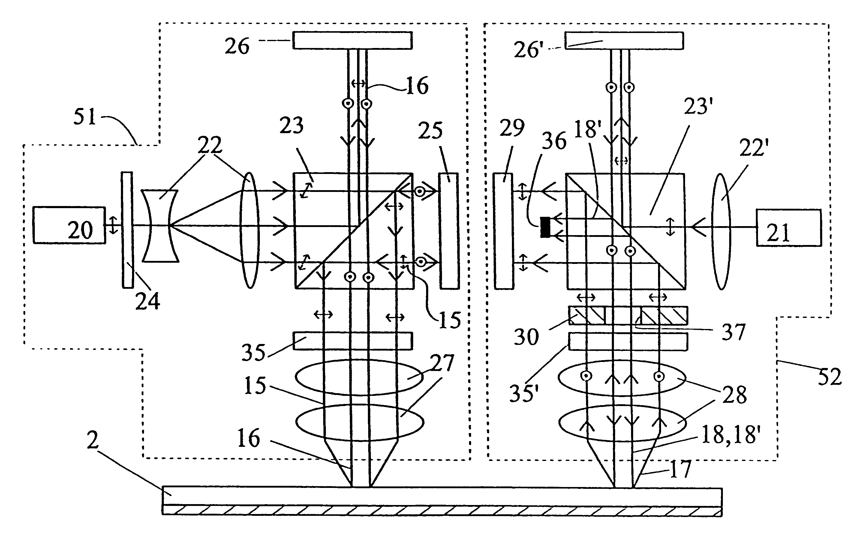
[0017]In a special embodiment of the holographic recording medium of the invention the reflection layer is a wavelength selective mirror reflecting on the read wavelength and transmitting or absorbing on the write wavelength. This arrangement greatly improves the sensitivity of the recording.
[0019]Advantageously, the wavelength of the writing length source of the apparatus of the invention is between 400-550 nm, and the wavelength of the reading light source is between 600-700 n. Such light source are readily available in the forms of laser diodes, allowing the construction of small and robust optical read / write systems. Other light sources, such as solid state lasers are also considered, because they provide higher energy levels.
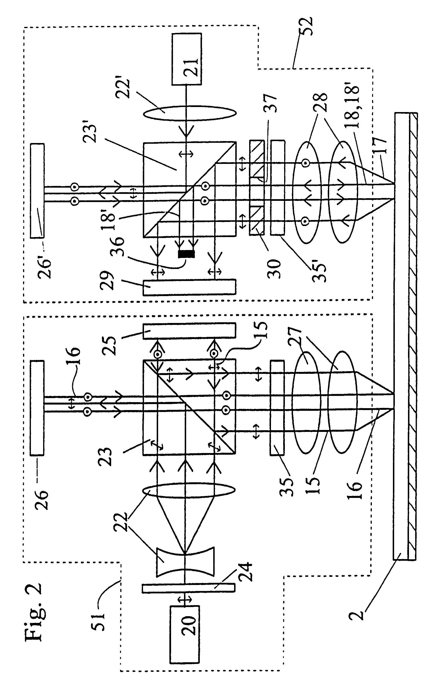
[0021]It is contemplated that the object beam and the reference beam in the read optics and / or the write optics have a common optical axis, and there is provided a polarisation selective beam splitter in combination with a polarisation wave plate and / or a beam stop for separating the reflected reference beam from the reflected object beam. This is feasible, because the polarisation holography technique suggested allows the separation of the reference beam from the object beam, and the SNR of the readout is high.
[0023]It has been found practical and feasible for the read optics and the write optics to have a common objective lens for imaging the reference and object beams onto a recording layer and for imaging the reflected object beams onto the read detector. Thereby the optical system may be compact and lightweight, and the positioning system is simpler. Also, direct readout after recording is possible, practically without any delay.
[0026]Using the advantageous properties of the holographic recording method and the recording medium of the invention, it is also proposed to implement a novel method for the coding of the recorded information on the holographic optical recording medium. The method comprises the recording of the information in the form of several discrete holograms and / or subholograms recorded in different physical and / or logical recording locations on the optical recording medium, preferably an optical card. These holograms or subholograms contain data sets, where the sequence of the data sets together constitute the recorded information. According to the inventive method, the data sets are recorded in a random sequence of the recording locations. If the sequence of the recording is not readily known, the access to the data is effectively blocked. The method requires relatively little excess memory capacity, but at the same time it is very effective.
[0028]In a further improved implementation, the location of the first data set is stored, and the location of the following data sets are stored in the previous data sets. It is especially foreseen that the physical recordings follow each other in an ordered sequence, but that the phase code addresses change randomly. Thereby the readout data rate can be maintained at a high level, but the encoding is still ensured. In an optional preferred realisation of the method, the random sequence of the data sets is stored and encrypted and / or made inaccessible for unauthorised users. This latter solution may facilitate the faster readout of the data.

Problems solved by technology

A number of solutions have been proposed for incorporating holograms into data storage cards, but the holograms is mostly used for authentication purposes, and not for data storage.
Using holograms to store data on a credit-card sized data card involves several problems.
These requirements are difficult to meet with a conventional plastic card.
There are very few erasable optical materials that are suitable for holographic recording, the achievable signal-to-noise ratio is relatively low and high exposition energy is needed.
To ensure the stability of the recorded holograms, different reading and writing wavelength is required, but in this case the reconstructed image of the hologram is distorted so much, that high-density storage is not possible.
A disadvantage of the proposed solution is that the mirror must be removed during readout, which makes this system unfit for practical optical recording systems.
Also, there is no suggestion to use this method with an optical card.
This known solution also require the use of a reference beam that is incident on the opposite surface of the photosensitive medium, so the solution is not practical for an optical card.
This method is not suitable for forming erasable and re-recordable holograms, and the optical system is very complicated.
However, this document does not address the problem of distortion caused by the difference in the wavelengths.
Therefore, the problem of wavelength distortion is not addressed either.
On the other hand, the disclosed complex waveguide head comprises expensive acousto-optical elements and other electro-optical devices which require very sophisticated control and power supply systems.
This optical head can not be manufactured in a cost-effective way with current technology.

Method used


Image

  • System and method for recording of information on a holographic recording medium, preferably an optical card
  • System and method for recording of information on a holographic recording medium, preferably an optical card
  • System and method for recording of information on a holographic recording medium, preferably an optical card

Examples


Embodiment Construction

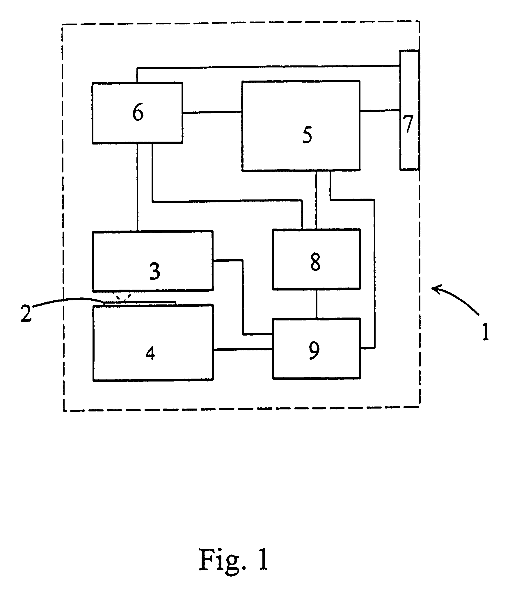
[0039]FIG. 1 shows the block diagram of the optical storage system 1 of the invention. The holographic optical storage system 1 comprises the optical recording medium. The medium is preferably an optical card 2, which is normally fixed on the card positioning unit 4. It must be emphasised that instead of the optical card, an optical disk or tape is also suitable to realise the invention. The optical card 2 is read and written (recorded) by the card read / write optics 3. The functions of the optical storage system 1 are controlled by the main controller 5, which is practically a microprocessor. The main controller 5 is controlling the data processor 6 and the synchronising circuit 8, and further the positioning controller 9. The main controller 5 is also connected to the interface 7. Data input and output are effected through the interface 7, and the data are processed by the data processor 6. Synchronising circuit 8 synchronises the read / write functions of the read / write optics 3 wit...


PUM


Abstract

The invention relates to a method for the recording and reading of data with a holographic write / read apparatus onto a holographic recording medium with a thin holographic recording layer. The medium is preferably an optical card (2). The recording of the information is in the form of data pages stored as thin Fourier holograms (61). According to the invention, it is foreseen to use reflected transmission and polarisation holography with different write and read wavelengths, and to correct during reading the distortion in the readout channel caused by the difference between the write and read wavelengths. The invention further relates to an apparatus and system for performing the method. There is also disclosed a method of coding the recorded information.

Description

TECHNICAL FIELD[0001]The present invention concerns a method and apparatus for the recording and reading of data on a recording medium, preferably an optical card, by holography. The invention also relates to an apparatus for use with the method of the invention. The apparatus uses a holographic recording medium, and holographic write / read optical system. The recording medium is preferably an optical card. It has a thin holographic recording layer, wherein the recording of the information is in the form of data pages stored as thin Fourier holograms. The invention further relates to a method of coding of the recorded information on a holographic optical recording medium. In the method, the information is recorded in the form of several discrete holograms recorded in different physical and / or logical recording locations on the optical recording medium, Each holograms containing data sets and the sequence of the data sets together constitute the recorded information.BACKGROUND ART[000...

Claims


Application Information

Patent Timeline
IPC IPC(8): G11B7/00G11B7/12G11B7/24
CPCG11B7/0033G11B7/0065G03H2001/2675G11B20/00086G11B20/00876G02B27/10G11B7/13G11B7/1374G11B7/1395G11B7/24044G11B20/22G11B2007/0003G11B2220/17
Inventor RAMANUJAM, P. S.HVILSTED, SORENKOPPA, PALLORINCZ, EMOKERICHTER, PETERSZARVAS, GABOR
Owner DANMARKS TEKNISKE UNIV
Learn More